External Axis
This document describes how to add an external axis. An additional stepper motor module is required to control the external axis.
Hardware Connections
Connect the external axis just like all other axes. See pinout below:

Configuration
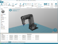
1. Switch on the robot and start CPRog/iRC. It takes about 20-30s for the embedded computer to boot, so that it can be connected in step 3.
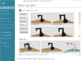
2. Click on "File". Then select your Robot type.
3. Click on Connect. Once connected, click on "File" again.
4. Click on "Configure Project"
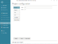
5. Click on "External Axes"
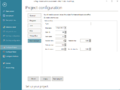
6. Configure your external Axis.


The values displayed on the last image above are the correct values for the optional linear axis that the robolink DP robots can travel on.
- Type: Leave this field blank, unless you know which xml robot configuration file you want to use for the external axis.
- Kinematic: Select independent. - At the time of writing only independent axes are supported. "Dependent" means that the robot is connected to the external axis and moves with it. Independent allows the external axis to be moved independently of the robot.
- CAN ID: This is the address of the stepper motor module of this axis. Normally the first external axis has the CAN ID 88, which corresponds to switch position 9 on the stepper motor module of the axis.
- Gear scale: Defines the gear-transmission-ratio. It should be set, so that the position displayed in the software corresponds to the distance the external axis has been moved. When position 1000 (mm) is displayed in the software, the robot should have moved 1m. Negative Values can be used to invert the direction of travel. (For a rotational external axis, this value would be the degrees (°) of rotation, i.e. the when 360 (°) is displayed in the software, the axis should have completed one rotation.
- Position min and Position max: define the joint limits to avoid collisions. A 1m external axis should be limited to a minimum of 0 (mm) or greater and a maximum of 1000 (mm) or smaller.
- Velocity max: is the maximum velocity that the axis is allowed to move at. For a linear axis this value is in mm/s. For a rotational axis this value is in °/s.
- Acceleration: defines the instant acceleration in mm/s² or °/s². (Initial acceleration from standstill)
- Acceleration Inc: defines the subsequent acceleration in mm/s² or °/s². (Subsequent acceleration, once the axis is moving)
7. Click on "Save project". The project is saved locally on the PC and also remotely on the embedded computer module. This operation may take up to 5s. To activate the changes, restart the robot (switch off, wait 10s switch on.)
8. Click on Connect. Once connected, click on "File" again
9. Click on "Configure Project" and verify that the changes that you made are still present.
Firmware Parameters (Advanced)
Any stepper motor module must be configured. For known axes this is done in the factory. However, there is a vast number of different types of motors/inis/encoders and joint configurations. For custom joints this process needs to be carried out by the user for the system to function as intended. The "Quality Management" sheet that comes with the electronics will indicated unconfigured for an additional axis, if the axis has not been configured.
Please refer to the article Firmware Parameter Configuration on how to change the parameters!
Referencing
Now you are ready to reference the robot including the external axis. Start at Step 2 in the link, since the robot is already connected in software right now.