Difference between revisions of "Digital Inputs / Outputs"
| Line 2: | Line 2: | ||
The CPR robolink control comes with a digital input / output module. This page shows how to connect actors, valves or sensors to the module. | The CPR robolink control comes with a digital input / output module. This page shows how to connect actors, valves or sensors to the module. | ||
| + | |||
The Digital IO module provides 7 digital inputs and 7 digital outputs. The inputs are decoupled by optocoupler and accept 24V input signals. The outputs are reed relays which can drive up to 500 mA per channel. | The Digital IO module provides 7 digital inputs and 7 digital outputs. The inputs are decoupled by optocoupler and accept 24V input signals. The outputs are reed relays which can drive up to 500 mA per channel. | ||
Revision as of 15:05, 2 July 2017
The CPR robolink control comes with a digital input / output module. This page shows how to connect actors, valves or sensors to the module.
The Digital IO module provides 7 digital inputs and 7 digital outputs. The inputs are decoupled by optocoupler and accept 24V input signals. The outputs are reed relays which can drive up to 500 mA per channel.
Indicators: When the state of a sensor input or and output changes the orange LED on the top is blinking once.
Output Usage: The output signals can be switched on or off with the 'Digital Out' command.
- The 'Local' parameter has to be 'true' to use the physical outputs. If it is 'false' the virtual global outputs are used.
- The 'Ch' channel parameter defines the output channel from 1 to 7
- The 'State' parameter tells CPRog to switch the output on 'true' or off 'false'
Please be aware that the outputs can only be switched on when the robot is enabled!
Attention: The outputs must not drive more then 500 mA, also not at startup! Avoid higher currents e.g. due to capaciators! Use a secondary relay in this this case.
Input Usage: The digital inputs can be used e.g. in if-then-else statements. The local and channel parameters are used as above.
Example
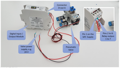
The picture on the right shows an output example: The first pin ( upper left line ) accepts the power supply for all outputs. The other seven lines are the outputs of the reed relays. This means, the relay connects, when switched on, the supply pin (first pin) with the according output pin.
For inputs its the same: the first pin is the ground pin, to be connected with the sensor ground. The sensor signal is connected with one of the seven input pins.
