Difference between revisions of "External Linear Axis in CPRog v980-10-XXX"
From Wiki
| Line 12: | Line 12: | ||
The stepper motor module will need new firmware parameters. These have to be configured using the [[Config_Software_ModuleCtrl|ModuleCtrl Software]]. | The stepper motor module will need new firmware parameters. These have to be configured using the [[Config_Software_ModuleCtrl|ModuleCtrl Software]]. | ||
#Install and start the ModuleCtrl software. | #Install and start the ModuleCtrl software. | ||
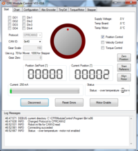
| − | #Select the correct CAN ID (hex) of your module. [[file:ModuleCtrl_page1.png|thumb|right| | + | #Select the correct CAN ID (hex) of your module. [[file:ModuleCtrl_page1.png|thumb|right|200px|Step 3. Select the correct CAN ID of your module and click connect.]] |
#*For an additional 4th axis this would be 0x40 (decimal 64 converted to hex). | #*For an additional 4th axis this would be 0x40 (decimal 64 converted to hex). | ||
#*For an additional 5th axis this would be 0x50 (decimal 80 converted to hex). | #*For an additional 5th axis this would be 0x50 (decimal 80 converted to hex). | ||
#Click "connect" | #Click "connect" | ||
# Switch to the | # Switch to the | ||
Revision as of 14:57, 20 November 2018
To use an external linear axis, an additional stepper motor module is required. That module needs to be configured upon receipt. Changes to the CPRog project file need to be made and a robot file for the external linear axis has to be installed and potentially adapted.
Module Configuration
Prior to supplying power to the module, set the switch on the top of the stepper motor module.
Configure rotary switch on the stepper motor module to the next available address:
- If configured as 4th axis, the switch on the module needs to be set to position "6". (In software this is (in decimal) joint ID 64
= 0x10 + 8 * <switch_position>) - If configured as 5th axis, the switch on the module needs to be set to position "8". (In software this is (in decimal) joint ID 80
= 0x10 + 8 * <switch_position>)
Firmware Paramters
The stepper motor module will need new firmware parameters. These have to be configured using the ModuleCtrl Software.
- Install and start the ModuleCtrl software.
- Select the correct CAN ID (hex) of your module.
- For an additional 4th axis this would be 0x40 (decimal 64 converted to hex).
- For an additional 5th axis this would be 0x50 (decimal 80 converted to hex).
- Click "connect"
- Switch to the
