Difference between revisions of "Remote Variable Access"
m |
|||
| (5 intermediate revisions by the same user not shown) | |||
| Line 3: | Line 3: | ||
=CRI Ethernet Interface= | =CRI Ethernet Interface= | ||
| − | Main article and documentation: [[ | + | Main article and documentation: [[CRI Ethernet Interface|CRI Ethernet Interface]] |
| + | |||
Variables must be declared and defined in the running robot program in order to be accessed. That means the store command must have been called in the robot program before the variable value can be read or set using the CRI. | Variables must be declared and defined in the running robot program in order to be accessed. That means the store command must have been called in the robot program before the variable value can be read or set using the CRI. | ||
| Line 18: | Line 19: | ||
=Camera interface= | =Camera interface= | ||
| − | + | The camera interface may be used to change variables if your version of CPRog/iRC or TinyCtrl does not support the SetVariable CRI commands. This interface is supported in CPRog/iRC V902-11-007 and TinyCtrl V980-11-085 and newer. | |
In order to use the camera interface you will need to program a TCP socket that simulates a IFM O2D camera by regularly sending values in the format specified below. CPRog/iRC or TinyCtrl then needs to be set up to connect to that socket and query the camera interface in the robot program. | In order to use the camera interface you will need to program a TCP socket that simulates a IFM O2D camera by regularly sending values in the format specified below. CPRog/iRC or TinyCtrl then needs to be set up to connect to that socket and query the camera interface in the robot program. | ||
| Line 24: | Line 25: | ||
==Protocol== | ==Protocol== | ||
Create a TCP socket at a port of your choice (eg. 50010) that regularly sends messages in the following format: | Create a TCP socket at a port of your choice (eg. 50010) that regularly sends messages in the following format: | ||
| + | |||
'''0000start<status>#<ignored>#<ignored>#<model class>#<x coord>#<y coord>#<rotation>#<ignored>stop''' | '''0000start<status>#<ignored>#<ignored>#<model class>#<x coord>#<y coord>#<rotation>#<ignored>stop''' | ||
| + | |||
| + | As of version 13-033 the following format is also supported. This format also includes a Z component. | ||
| + | |||
| + | '''0000startM<model class>#<object count>O<x coord>#<y coord>#<z coord>#<orientation>#stop''' | ||
| + | |||
| + | Example: ''0000startM2#1O90.607#526.516#-0.000#94.80#stop'' | ||
| + | |||
{| | {| | ||
|<status> | |<status> | ||
| Line 34: | Line 43: | ||
|<model class> | |<model class> | ||
|integer | |integer | ||
| + | |- | ||
| + | |<object count> | ||
| + | |set to 0 if no object is detected, otherwise 1 | ||
|- | |- | ||
|<x coord> | |<x coord> | ||
| − | |x | + | |pixel x coordinate (integer) or cartesian X coordinate in mm. The pixel coordinate is offset by 320 or 640 depending on the message format. |
|- | |- | ||
|<y coord> | |<y coord> | ||
| − | |y | + | |pixel y coordinate (integer) or cartesian Y coordinate in mm. The pixel coordinate is offset by 240 or 480 depending on the message format. |
| + | |- | ||
| + | |<z coord> | ||
| + | |cartesian Z coordinate in mm | ||
|- | |- | ||
|<rotation> | |<rotation> | ||
| Line 45: | Line 60: | ||
|- | |- | ||
|} | |} | ||
| + | |||
| + | As of version 13-033 the coordinate transformation can be disabled in the camera interface configuration. This means the X/Y/Z values of the camera will be available in the robot program without changes. | ||
==Interface configuration== | ==Interface configuration== | ||
| + | [[File:Camera_Configuration.PNG|thumb]] | ||
Open the camera configuration (File -> Configure Interfaces -> Cameras), select IFM O2D and click Add Camera. | Open the camera configuration (File -> Configure Interfaces -> Cameras), select IFM O2D and click Add Camera. | ||
| + | |||
| + | In version V13-033 or newer: Select "Robot Coordinates (mm)" to get the unchanged coordinate values in your robot program. | ||
| + | |||
| + | In older versions enter the following settings: | ||
* Check the enabled box | * Check the enabled box | ||
* Set the IP address and port of your TCP socket | * Set the IP address and port of your TCP socket | ||
| Line 55: | Line 77: | ||
* Set Up to (1, 0, 0) | * Set Up to (1, 0, 0) | ||
Then save your project with the button below. TinyCtrl must be connected to update its configuration. | Then save your project with the button below. TinyCtrl must be connected to update its configuration. | ||
| − | |||
| − | |||
==Query values in robot program== | ==Query values in robot program== | ||
Latest revision as of 11:56, 20 January 2023
Variables are usually read and changed within a robot program. In case variables need to be set by a remote control either the CRI interface or the camera interface can be used, depending on the version of CPRog/iRC and TinyCtrl.
CRI Ethernet Interface
Main article and documentation: CRI Ethernet Interface
Variables must be declared and defined in the running robot program in order to be accessed. That means the store command must have been called in the robot program before the variable value can be read or set using the CRI.
The CRI commands to read variables are supported in CPRog/iRC V902-11-007 and TinyCtrl V980-11-085 and newer:
- GetNrVariable
- GetPosVariable
The CRI commands to change variables are supported in CPRog/iRC V902-11-011 and TinyCtrl V980-11-088 and newer:
- SetVariableSingle
- SetVariablePosCart
- SetVariablePosJoint
Please refer to the CRI documentation on how to use these commands.
Camera interface
The camera interface may be used to change variables if your version of CPRog/iRC or TinyCtrl does not support the SetVariable CRI commands. This interface is supported in CPRog/iRC V902-11-007 and TinyCtrl V980-11-085 and newer.
In order to use the camera interface you will need to program a TCP socket that simulates a IFM O2D camera by regularly sending values in the format specified below. CPRog/iRC or TinyCtrl then needs to be set up to connect to that socket and query the camera interface in the robot program.
Protocol
Create a TCP socket at a port of your choice (eg. 50010) that regularly sends messages in the following format:
0000start<status>#<ignored>#<ignored>#<model class>#<x coord>#<y coord>#<rotation>#<ignored>stop
As of version 13-033 the following format is also supported. This format also includes a Z component.
0000startM<model class>#<object count>O<x coord>#<y coord>#<z coord>#<orientation>#stop
Example: 0000startM2#1O90.607#526.516#-0.000#94.80#stop
| <status> | PASS / FAIL, if FAIL the model class will be -1 and the coordinates will be ignored |
| <ignored> | any number |
| <model class> | integer |
| <object count> | set to 0 if no object is detected, otherwise 1 |
| <x coord> | pixel x coordinate (integer) or cartesian X coordinate in mm. The pixel coordinate is offset by 320 or 640 depending on the message format. |
| <y coord> | pixel y coordinate (integer) or cartesian Y coordinate in mm. The pixel coordinate is offset by 240 or 480 depending on the message format. |
| <z coord> | cartesian Z coordinate in mm |
| <rotation> | A value (float) |
As of version 13-033 the coordinate transformation can be disabled in the camera interface configuration. This means the X/Y/Z values of the camera will be available in the robot program without changes.
Interface configuration
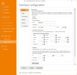
Open the camera configuration (File -> Configure Interfaces -> Cameras), select IFM O2D and click Add Camera.
In version V13-033 or newer: Select "Robot Coordinates (mm)" to get the unchanged coordinate values in your robot program.
In older versions enter the following settings:
- Check the enabled box
- Set the IP address and port of your TCP socket
- Set ScaleX and ScaleY to 1 or lower if you need more precision
- Set Origin to (0, 0, 0)
- Set Look to (0, 0, 1)
- Set Up to (1, 0, 0)
Then save your project with the button below. TinyCtrl must be connected to update its configuration.
Query values in robot program
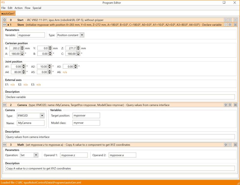
In order to read the values in the robot program the Camera command must be used. The x, y and A values will be written into the target position variable and the model class will be written to the model class number variable. If you need x, y, z coordinates you may use the Math-Set command to copy the A value to the z element.

