Difference between revisions of "Motor Brake"
m |
|||
| (6 intermediate revisions by 2 users not shown) | |||
| Line 1: | Line 1: | ||
| − | + | Motor brakes are used to prevent robot from falling down or collapsing when there is no motor torque, e.g. in the case of an emergency stop. They are used in gantry and SCARA robots z-axis. | |
| − | + | This article explains how to integrate a motor brake into a stepper control. For BLDC controls please refer to the circuit diagram linked in [[Documentation]]. | |
| − | + | [[file:caution.png|left|25px]] Caution! Hot plugging can damage the electronics! Disconnect the control from power before working on it. Test the brake functionality before releasing the robot to normal operation. | |
| + | Software version V13-033 or higher is required. | ||
| − | + | = Necessary Connections = | |
| − | + | To provide a reliable brake functionality the following connections have to be present: | |
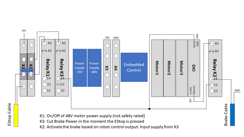
| + | * Relay K2: This relay is operated by the robot control. It supplies power to the brake as soon as the motor can provide the necessary torque. | ||
| + | * Connection DOut21 to K2: Necessary to operate the brake relay | ||
| + | * Relay K3: operated directly by the emergency stop this relay cuts the brake power as soon as the e-stop is pressed. K3 provides the input for K2. | ||
| + | * Connection K3-Out (or EStop status) to DIn21: Necessary in specific cases to prevent a too early brake release | ||
| − | Bremsverschaltung_230125.png | + | [[file:Bremsverschaltung_230125.png|800px]] |
| − | + | In the above schematics only the signal lines are shown, the 24V or Ground connections are only hinted. | |
| − | + | Please see also the following schematics: [https://cpr-robots.com/download/igusRobotControl/Documentation/iRC_CircuitDiagram_48V_EN.pdf iRC_CircuitDiagram_48V_EN.pdf - to be extended, Connection K3-Out to DIn21 ist not included here] | |
| − | + | = Necessary Software Configuration = | |
Version V13-033 or higher is required for this set up. Please update your software if the robot runs an older version. | Version V13-033 or higher is required for this set up. Please update your software if the robot runs an older version. | ||
The following settings have to be done in the iRC while the robot is connected: | The following settings have to be done in the iRC while the robot is connected: | ||
| Line 22: | Line 27: | ||
* Apply and save the changes | * Apply and save the changes | ||
| + | [[file:IRC_EnableBrake.PNG|left]] | ||
| − | + | [[Category:Configuration]][[Category:CPRog]][[Category:TinyCtrl]] | |
Latest revision as of 10:15, 4 July 2024
Motor brakes are used to prevent robot from falling down or collapsing when there is no motor torque, e.g. in the case of an emergency stop. They are used in gantry and SCARA robots z-axis.
This article explains how to integrate a motor brake into a stepper control. For BLDC controls please refer to the circuit diagram linked in Documentation.
Caution! Hot plugging can damage the electronics! Disconnect the control from power before working on it. Test the brake functionality before releasing the robot to normal operation.
Software version V13-033 or higher is required.
Necessary Connections
To provide a reliable brake functionality the following connections have to be present:
- Relay K2: This relay is operated by the robot control. It supplies power to the brake as soon as the motor can provide the necessary torque.
- Connection DOut21 to K2: Necessary to operate the brake relay
- Relay K3: operated directly by the emergency stop this relay cuts the brake power as soon as the e-stop is pressed. K3 provides the input for K2.
- Connection K3-Out (or EStop status) to DIn21: Necessary in specific cases to prevent a too early brake release
In the above schematics only the signal lines are shown, the 24V or Ground connections are only hinted.
Please see also the following schematics: iRC_CircuitDiagram_48V_EN.pdf - to be extended, Connection K3-Out to DIn21 ist not included here
Necessary Software Configuration
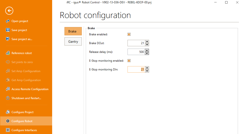
Version V13-033 or higher is required for this set up. Please update your software if the robot runs an older version. The following settings have to be done in the iRC while the robot is connected:
- Enable the brake and set the according digital out: normally DOut21
- Enable the E-Stop monitoring and set the according digital in: normally DIn21
- Apply and save the changes

