Difference between revisions of "Referencing the Mover Robot Arm"
From Wiki
(→g) |
|||
| Line 6: | Line 6: | ||
If you cannot move the robot to an upright position because of the software limits, move it as far as possible in the corresponding direction, set the axes to zero as described and repeat the procedure until the position is reached. | If you cannot move the robot to an upright position because of the software limits, move it as far as possible in the corresponding direction, set the axes to zero as described and repeat the procedure until the position is reached. | ||
| − | + | <gallery> | |
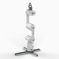
| − | + | File:Mover4_upright.jpg|Pic. 1: Mover4 upright Position | |
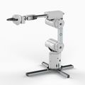
| − | + | File:Mover6_upright.jpg|Pic. 2: Mover6 upright Position | |
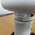
| − | + | File:Mover_zeromark.JPG|Pic. 3: Zero-mark | |
| + | File:Mover_setjointstozero.jpg|Pic. 4: Menue entry | ||
| + | </gallery> | ||
Revision as of 09:46, 3 September 2018
Prior to working with the Mover, you should perform an axis referencing so that the visualization in the software matches the real robot.
- Move the robot to its zero position using the jog keys (bottom left in CPRog) (Pic. 1&2).
- The axis markers must point to the edge of the housing parts (Pic. 3).
- Then select "Configuration -> Set Joints to Zero" from the logo menu and confirm with "OK" (Pic. 4).
If you cannot move the robot to an upright position because of the software limits, move it as far as possible in the corresponding direction, set the axes to zero as described and repeat the procedure until the position is reached.


