Difference between revisions of "Config Software ModuleCtrl"
| Line 61: | Line 61: | ||
# Select CAN ID of the module under test. 0x10 for the base joint (joint1), 0x20 for joint 2, 0x30 for joint 3,... | # Select CAN ID of the module under test. 0x10 for the base joint (joint1), 0x20 for joint 2, 0x30 for joint 3,... | ||
# Click "Connect". The Statuas message changes from "not connected" to a different value. | # Click "Connect". The Statuas message changes from "not connected" to a different value. | ||
| − | #* "module dead" means that the module with the CAN ID selected above is not responding. Change the ID. The [http://www.cpr-robots.com/products/mover4.html Mover4 robot arm] has the IDs 0x10, 0x20, 0x30 and 0x40 for the joints starting at the base joint. | + | #* "module dead" means that the module with the CAN ID selected above is not responding. Change the CAN ID in ModuleCtrl. The [http://www.cpr-robots.com/products/mover4.html Mover4 robot arm] has the IDs 0x10, 0x20, 0x30 and 0x40 for the joints starting at the base joint. |
#* If you are using [[media:DINrail AEME.png|DIN rail modules]], e.g. with a robolink robot, you should see a [[media:DIN-Rail-Module-LEDs.png| blinking green LED]] at the top of the module, indicating CAN communication with the module. | #* If you are using [[media:DINrail AEME.png|DIN rail modules]], e.g. with a robolink robot, you should see a [[media:DIN-Rail-Module-LEDs.png| blinking green LED]] at the top of the module, indicating CAN communication with the module. | ||
# "com watch dog" or similar error message other then "module dead" means that the module answers, but is still in an error statew. That is expected after start up and before clicking "Reset". | # "com watch dog" or similar error message other then "module dead" means that the module answers, but is still in an error statew. That is expected after start up and before clicking "Reset". | ||
Revision as of 22:45, 14 May 2018
ModuleCtrl is used to set firmware parameters and to diagnose/test single joints. It can read / set the control loop parameters of the joints.
Requirements:
- Windows XP, 7, 10,
- .net framework 3.5 sp1 or higher
- Microsoft Chart Controls
Download:
Parameter Configuration
For the Mover robots the joint controller parameter define how the robot moves: more smooth, or more precise
- Smooth motion: Position-P = 0,5, Velocity-P = 0.5, I and D values 0
- Precise motion: Position-P = 1.5, Velocity-P = 0.6, I and D values 0
Robots build in 2016 or later should set the joint 4 settings to Position-P = Velocity-P = 0.3. This joint features a motor with a better encoder.
Joints 5 and 6 of the Mover6 cannot be configured in this way.
Whatever you do, do not hot plug! Hot plugging the stepper motors while active will almost certainly cause damage to the electronics
ModuleCtrl Manual
The software ModuleCtrl is a diagnostics and configuration tool for the CPR motion control electronics.
Installation
Double-click on the installer and follow the directions.
Safety
This tool allows direct read and write access to sensitive firmware parameters.
- Always stay out of reach of the robot
- Always have the emergency stop in reach
- When changing any values, start with small changes and small motions
- Start with a 'fault tolerant' robot axis, such as joint 1, which can rotate a long way without collision, or joint 4 which is small.
Operation
Start-Tab
Connect
Do not hot plug! Never connect or disconnect any component, while mains power is connected. Always disconnect mains supply prior to working on the electronics. Disconnecting or connecting the motors while powered will almost certainly result in damage to the electronics.
- Switch OFF the robot and the control electronics. Disconnect power supply from the mains.
- Connect the USB-to-CAN adapter to the control electronics, establish all physical connections now, prior to powering on the control electronics. Never unplug any connector while power is supplied to the control electronics or the robot.
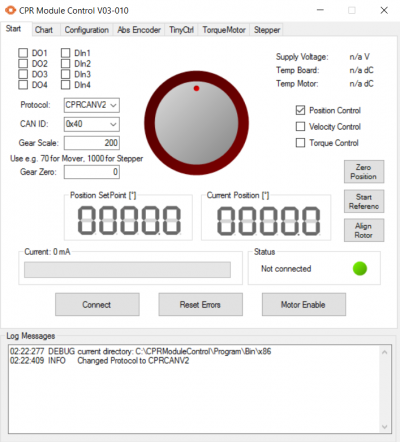
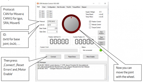
- Select CAN Protocol. CPRCAN for Mover 4, CPRCANV2 for igus robots, SRA, Mover6.
- Select CAN ID of the module under test. 0x10 for the base joint (joint1), 0x20 for joint 2, 0x30 for joint 3,...
- Click "Connect". The Statuas message changes from "not connected" to a different value.
- "module dead" means that the module with the CAN ID selected above is not responding. Change the CAN ID in ModuleCtrl. The Mover4 robot arm has the IDs 0x10, 0x20, 0x30 and 0x40 for the joints starting at the base joint.
- If you are using DIN rail modules, e.g. with a robolink robot, you should see a blinking green LED at the top of the module, indicating CAN communication with the module.
- "com watch dog" or similar error message other then "module dead" means that the module answers, but is still in an error statew. That is expected after start up and before clicking "Reset".
- Click "Reset" to reset any errors. The new status should be (0x04) "Motor not enabled".
- Click the "Enable". Now the status message should change to "no error"
Move the joint
- The speed of the motion depends on the selected GearScale.
- Refer to the Robot ini file to set the correct value (approx. 65 for Mover4, 278 for igus robolink, 5000 for SRA).
- Start with small motions
- Keep one hand placed on the emergency stop when moving the large center wheel or changing values.
Now you can move the joint with the center wheel.
Zero Position
Defines the current position as 0. To activate the new position, click "Reset" and then "Enable".
Start Reference
The joint may need to be driven manually into an appropriate position before starting the referencing operation.
- The joint module starts the reference search motion as specified in the "Stepper" tab
until it finds the reference switch/sensor. This could be a linear motion, or an oscillation motion
- Speed and direction of the motion can be changed in the "Stepper" tab
- The user is expected to observe the motion and stop (if necessary, emergency stop switch) the motion and stop if it does not work as intended. There are no software safety limits (of motion) set in this diagnostics software. The user is expected to closely observe and take appropriate action to prevent potential damage.
- Manually move the joint close to the reference switch/sensor.
- If you have the modular control electronics, locate the module with the blinking green LED.
- Observe the status of the orange LED, while slowly moving the joint using the center wheel in the software. Once the orange LED lights up, the joint is at the reference switch.
- Move the joint a small distance away from that switch, so that the orange LED is off.
- Click "start reference" to start the reference motion. This only works, if the joint module has been configured for this. This is typical for stepper driver in the modular robot control electronics (e.g. the electronics used for the robolink robots).
- Once the Robot finds the reference switch/sensor, the joint module stops and resets its position to a value specified in the Stepper tab, or it starts a search motion to touch the reference switch from both sides with reduced velocity. This behavior can be defined in the "Stepper" tab of the ModuleCtrl software.
Align Rotor
Only applicable to torque motor: moves the rotor, to a specified position and aligns the rotor value with the motor encoder value.
GearScale and GearZero
The CPR communication protocols send set-point values the unit "encoder tics" to the joint modules. A "tic" corresponds to different amounts of movement depending on encoder type location. The calibration value "GearScale" and offset value "GearZero" can be set here.
- A small value corresponds to a small, slow motion.
- A large value corresponds to a big, fast, potentially unexpected motion.
- The motion may be so fast that it causes the motors to stall.
- GearScale is approx. 65 for Mover4, 278 for igus robolink, 5000 for SRA.
Position Control, Velocity Control and Torque Control
The three checkboxes at on the right side of the ModuleCtrl window define the type of control used.
- Position control uses the encoder values to move the joint to the position defined by the center wheel.
- In velocity control, the center wheel defines the speed of the joint movement.
- Torque control is available only in very few joint modules.
Chart-Tab
Using the "Chart"-tab a sine motion can be applied to the drive. Further parameter like the current or the remaining error are displayed over the time on the chart. This is useful to test motors and encoders.
- Speed: Sets the speed of the sine motion from 0% to 100%. Try without connected joint at first and start with small values.
- Amplitude of the motion in °
- The start check box starts the motion. The motion setpoint starts at zero, or resumes at the last value after interruption.
Confguration-Tab
Using the "Configuration"-tab the main firmware parameters of a motor module can be set.
- Press "Read Configuration" to load the data from the board
- Update the data. E.g. set "overcurrent" to zero to disable the overcurrent monitoring.
- Press "Set" besides the text field to write your settings to the board.
XXX incomplete
AbsEncoder-Tab
Reading / changing of parameters for joint-integrated absolute encoder. XXX incomplete
TinyCtrl-Tab
If TinyCtrl is running on a single board computer, e.g. the Phytech Linux board, this tab allows the shutdown of TinyCtrl. The shutdown of the TinyCtrl program on the Linux board is necessary, to establish a connection to a single module using ModuleCtrl.
TorqueMotor-Tab
Reading / changing of parameter for torque motor joints. XXX incomplete
Stepper-Tab
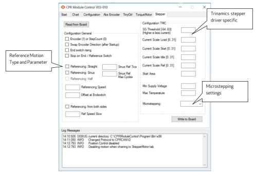
Firmware version 0x42-0x020B, April 2017 Reading and writing from and to firmware requires a Connection to a stepper module.
- "Read from Board" reads the firmware parameters of the currently selected module.
- "Write to Board" writes the firmware parameters displayed on this page to the selected module.
- Encoder (1) or StepCount (0): If checked the joint works closed loop with a quadrature encoder.
- If unchecked then an open loop algorithms is used instead: The joint position changes based on the commanded steps. This only works, if there is a small, constant load. A motor stall will not be detected.
- The StepCount value should only be used with microstepping up to 1:64 (see microstepping setting below), especially with higher velocities.
- End switch rising:
- When checked then the module reacts on a rising edge of the end switch.
- When unchecked the module reacts on a falling edge.
- Stop on end switch: When checked, the joint always stops when reaching an end switch
- Referencing Mode:
- Straight/Linear: The joint moves with the speed and direction defined in "Referencing Speed" until the defined change in the signal from the reference switch is detected (also see bullet point "End switch Rising" above). Afterward a slower, higher precision, search is triggered, or the position is stored directly. This method method requires the joint to be on the correct side before starting the reference motion!
- Sinus: The joint will perform an oscillating motion with increasing amplitude.
- The amplitude increments are defined in "Sinus Ref Tics".
- The maximum number of cycles is defined in "Sinus Ref Max Cycle".
- The motion speed is defined by "Referencing Speed", but the sign of this speed is ignored here. To avoid damage in case of a collision, a the "Current Scale Ref" can be set, which would use less than usual motor current. "Less than Usual" means a value less than "CurrentScale Load" (also see bullet point below).
- Referencing: Half – Not implemented yet
- Referencing speed: The velocity used for the reference motion, integer value. Start with small values. Use negative numbers to change direction.
- Offset at Endswitch: When reaching the reference switch, the joint position is set to this value. This allows to adjust differences between the zero position and the reference switch. Positive and negative integer values are allowed.
- Referencing from both sides: To find a more precise reference point a more precise search motion can be triggered after reaching the reference switch for the first time during referencing. The module then moves twice across the reference switch with low speed, so that two trigger points approaching from the right and from the left are found. The reference point is defined as the middle. The "Offset at Endswitch" (see above) is then added.
- Ref Speed Slow: For this slower, more precise search motion, a smaller velocity can be set using this variable.
Section Configuration TMC
We use various Trinamic TMC stepper drivers (e.g. TMC 2660) for the modular control electronics. They allow operation with variable current using the StallGuard2 and CoolStep technologies. These algorithms need to be parametrized. Please refer to the chip datasheet for an explanation of the parameters. In short:
- SG Threshold: Parameter parametrizing the StallGuard functionality
- Current Scale: The max Current allowed during operation, from 0 (1/31 of the full possible current) to 31 (full current). This also defines the minimal current which is a fraction of this value. The StallGuard and CoolStep technologies adapt the motor current within these limits, depending on motor load. Increase this value if the motor stalls.
- CurrentScale Load: Current Scale when the joint is moving.
- CurrentScale Start: Current Scale when accelerating or moving at low rpm
- CurrentScale Idle: Current Scale when the joint is not moving this setting is applied.
- CurrentScale Referencing: Current Scale used during referencing. It allows e.g. to set a lower value for referencing than during operation to avoid damage when the joint accidentally collides e.g. during sinus reference motion.
- Microstepping: Allows to set the microstepping from 1 (full step) to 1/256. The most smooth motions are possible with 1/256 microstepping. When operating without encoder a microstepping of 1/64 or lower is recommended due to increased load on the microcontroller.


