Additional DIO-Boards of the DCi Control Electronics
The DCi Robot is shipped with one DIO module as standard. Should you require additional digital inputs and outputs, two additional DIO modules can be added. The hardware installation is simple, however, you need to get access to the underside of the robot.
Hardware installation
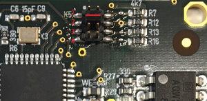
If there is only the standard DIO module installed, bridge the second pin-set of header K5 as shown in figure 1 using the jumper supplied with the module. (If there are already two DIO modules installed, bridge pin-pair 3 of K5.)
- Bring the robot into the referencing position, so that you can later turn it on its side.
- Turn off the robot and disconnect from power source.
- Turn the robot on its side. Once flipped one its side. You will see the electronics modules installed in the robot.
- Remove the four M3 hex nuts from one of the exposed modules and connect the four stand-off hex spacers supplied with the new DIO module.
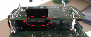
- Now carefully insert the module while making sure that the bus connector lines up and all pins get inserted into their socket counterparts (figure 2).
- Fix the module using the existing M3 lock nuts.
Software configuration
If you were to switch on the robot after the hardware installation, you would notice that the green LED of the newly installed DIO module is not blinking. That means that The software is currently not communicating with that module. Two changes need to be made. Once change in a project file of the computer embedded in the robot and one change in a project file in CPRog.
Embedded Control
You need to get FTP or Putty access to the embedded linux board. FTP access is described in Section 1 and 2 of the document available here: FTP_and_putty_Access
- Edit the file
\home\root\TinyCtrl\Data\Projects\EmbeddedCtrl.prj - In that file, find the entry
<DIOModule ID="112"/> - Right behind that entry, enter
, to activate the second DIO module<DIOModule ID="144"/>, to activate the third DIO module
- If you have two DIO modules installed in total, you file should look similar to this
...
<DIOModule ID="112"/> <DIOModule ID="128"/>
...
- If you have three DIO modules installed in total, you file should look similar to this
...
<DIOModule ID="112"/> <DIOModule ID="128"/> <DIOModule ID="144"/>
...
- Save the file under the same name and copy it into the same directory on the embedded linux board
\home\root\TinyCtrl\Data\Projects\EmbeddedCtrl.prj - Restart the robot to activate the changes. You should notice that after about 20s the green LEDs of both DIO modules are blinking. (The green LEDs of the motor modules will be blinking as well)
CPRog
Open CPRog and check, which project file you are using for the DCi robot. You can find the name of the project file in the title-bar of CPRog, when the window is not maximised.
- Locate and edit the file with that name in the CPRog project directory, which is by default located in c:\CPRog\Data\Projects\
- In that file, find the entry
<DIOModule ID="112"/>. This activates the existing DIO module. - Right behind that entry, enter
<DIOModule ID="128"/>, to activate the second DIO module<DIOModule ID="144"/>, to activate the third DIO module
- If you have two DIO modules installed in total, you file should look similar to this
...
<DIOModule ID="112"/> <DIOModule ID="128"/>
...
- If you have three DIO modules installed in total, you file should look similar to this
...
<DIOModule ID="112"/> <DIOModule ID="128"/> <DIOModule ID="144"/>
...
- Save the file.
- Close CPRog
- Open CPRog
- You should now have access to the Additional module(s)
Addressing the DIO channels
To address the channels in a Robot program works in the same way as before:
- DIO channels of the first DIO module are
- DIn21, DIn22, DIn23,... and DOut21, DOut22, DOut23,...
- DIO channels of the second DIO module (if installed) are
- DIn31, DIn32, DIn33,... and DOut31, DOut32, DOut33,...
- DIO channels of the third DIO module (if installed) are
- DIn41, DIn42, DIn43,... and DOut41, DOut42, DOut43,...

