Difference between revisions of "Additional DIO-Modules"
From Wiki
| Line 35: | Line 35: | ||
=Software Integration= | =Software Integration= | ||
*Open your project file, e.g. C:\CPRog\Data\Projects\51_IGUS_arm5DOF_SV.prj with and editor. | *Open your project file, e.g. C:\CPRog\Data\Projects\51_IGUS_arm5DOF_SV.prj with and editor. | ||
| − | *Find the line with the <DIOModule> Tag, e.g. line 30. | + | *Find the line with the <code><DIOModule></code> Tag, e.g. line 30. |
*Add one (for one additional module) or two lines (for two additional modules) as follows. | *Add one (for one additional module) or two lines (for two additional modules) as follows. | ||
*The number in the ID tag is the CAN ID in decimal writing. | *The number in the ID tag is the CAN ID in decimal writing. | ||
Revision as of 14:18, 18 June 2018
Scope
The Commonplace Robotics control for the igus robolink robots comes with one digital input / output module with seven digital inputs (24V via Optocoupler) and 7 digital outputs (24V max 300 mA via reed relay). If these DIOs are not enough it is possible to add two further digital input / output modules to the control.
Mechanical Integration
![]() Do not hotplug! Disconnect the control from the power source before changing components of plugging / unplugging cables!
Do not hotplug! Disconnect the control from the power source before changing components of plugging / unplugging cables!
- Add the bus extenders to the control. They have to be pressed in the C-Rail and pressed to the existing control beneath the Digital IO module.
- Plug the additional digital IO module
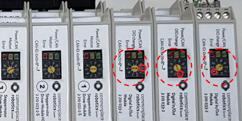
- Set the CAN ID with the selector on the front face:
- First (already existing) IO module: 0 (this results in CAN ID 0x70 = 112)
- Second (additional) IO module: 2 (this results in CAN ID 0x80 = 128)
- Third (additional) IO module: 4 (this results in CAN ID 0x90 = 144)
Electrical Integration
Digital Inputs:
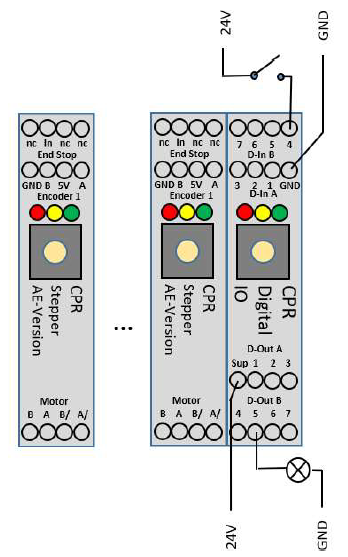
- Connect the ground pin (Output connector 1, to GND
- Supply 24V to one of the input pins
- Example on the left: 24V via switch to input pin 4
- Result in CPRog: digital input Din24 is triggered
Digital Outputs
- Connect the supply pin to 24V power supply
- The supply is forwarded to one of the outputs pins via reed relays
- Connect a valve or another component to the output pin
- Connect the component to GND to close the electrical circuit
- See the example with the lamp on output 5 on the left.
- In CPRog:
- Reset and Enable the robot
- Set DOut 25 to true to switch on the lamp
Software Integration
- Open your project file, e.g. C:\CPRog\Data\Projects\51_IGUS_arm5DOF_SV.prj with and editor.
- Find the line with the
<DIOModule>Tag, e.g. line 30. - Add one (for one additional module) or two lines (for two additional modules) as follows.
- The number in the ID tag is the CAN ID in decimal writing.
The first line <DIOModule ID="112"> should exist already.
<DIOModule ID="112">
<DIOModule ID="128">
<DIOModule ID="144">

