Difference between revisions of "Additional DIO-Modules"
From Wiki
(Updated) |
|||
| Line 1: | Line 1: | ||
| − | + | The Commonplace Robotics control for comes with one digital input / output (DIO) module with seven digital inputs (24V via Optocoupler) and 7 digital outputs (24V max 300 mA via reed relay). | |
| − | The Commonplace Robotics control for | + | If these DIOs are not enough it is possible to add two further DIO modules to the control for a total number of 21 inputs and outputs. |
| − | If these DIOs are not enough it is possible to add two further | ||
| − | + | This article explains the mechanical, electrical and software setup that is needed to add additional DIO modules. | |
| − | |||
| − | |||
| − | + | Please read the [[Documentation|User Guide]] for more information and wiring examples. | |
| − | |||
| − | + | =Mechanical Integration= | |
| − | |||
| − | |||
[[file:Caution.png|frameless|50px]] Do not hotplug! Disconnect the control from the power source before changing components of plugging / unplugging cables! | [[file:Caution.png|frameless|50px]] Do not hotplug! Disconnect the control from the power source before changing components of plugging / unplugging cables! | ||
| Line 22: | Line 16: | ||
**Third (additional) IO module: 4 (this results in CAN ID 0x90 = 144) | **Third (additional) IO module: 4 (this results in CAN ID 0x90 = 144) | ||
[[file:DIO_bus_settings.png|DIO_bus_settings.png]] | [[file:DIO_bus_settings.png|DIO_bus_settings.png]] | ||
| − | + | ||
| + | =Electrical Integration= | ||
[[file:DIO_pinout.png|thumb|400px|left]] | [[file:DIO_pinout.png|thumb|400px|left]] | ||
| − | + | ==Digital Inputs== | |
* Connect the ground pin (Output connector 1, to GND | * Connect the ground pin (Output connector 1, to GND | ||
* Supply 24V to one of the input pins | * Supply 24V to one of the input pins | ||
| Line 30: | Line 25: | ||
* Result in CPRog/iRC: digital input Din24 is triggered | * Result in CPRog/iRC: digital input Din24 is triggered | ||
| − | + | ==Digital Outputs== | |
*Connect the supply pin to 24V power supply | *Connect the supply pin to 24V power supply | ||
*The supply is forwarded to one of the outputs pins via reed relays | *The supply is forwarded to one of the outputs pins via reed relays | ||
| Line 42: | Line 37: | ||
<br clear=all> | <br clear=all> | ||
| − | + | =Software Integration= | |
| − | * | + | * Connect CPRog/iRC to the robot control. |
| − | * | + | * Open the configuration by clicking File -> Configure Project -> I/Os |
| − | + | * In the DIN rail I/O section set the number of modules | |
| − | * | + | * Optional: Name the inputs and outputs and set the reset and error states. |
| − | + | * Click Save project | |
| − | + | * Wait for at least 30 seconds, then restart the robot control and reload the project in iRC | |
| − | |||
| − | |||
| − | |||
| − | |||
| − | |||
| − | |||
| − | |||
| − | |||
| − | |||
| − | |||
| − | |||
| − | |||
| − | |||
| − | |||
| − | |||
| − | |||
| − | |||
| − | |||
| − | |||
| − | |||
| − | |||
| − | |||
| − | |||
| − | |||
| − | |||
| − | |||
| − | |||
| − | |||
| − | |||
| − | |||
| − | |||
| − | |||
| − | |||
| − | |||
| − | |||
| − | |||
| − | |||
| − | |||
| − | |||
| − | |||
| − | |||
| − | |||
| − | |||
| − | |||
| − | |||
| − | |||
| − | |||
| − | |||
| − | |||
| − | |||
| − | |||
| − | |||
| − | |||
| − | |||
| − | [[Category:robolink]][[Category:CPRog]][[Category:DIO_Modules | + | [[Category:robolink]][[Category:CPRog]][[Category:DIO_Modules]] |
Latest revision as of 11:24, 18 August 2022
The Commonplace Robotics control for comes with one digital input / output (DIO) module with seven digital inputs (24V via Optocoupler) and 7 digital outputs (24V max 300 mA via reed relay). If these DIOs are not enough it is possible to add two further DIO modules to the control for a total number of 21 inputs and outputs.
This article explains the mechanical, electrical and software setup that is needed to add additional DIO modules.
Please read the User Guide for more information and wiring examples.
Mechanical Integration
![]() Do not hotplug! Disconnect the control from the power source before changing components of plugging / unplugging cables!
Do not hotplug! Disconnect the control from the power source before changing components of plugging / unplugging cables!
- Add the bus extenders to the control. They have to be pressed in the C-Rail and pressed to the existing control beneath the Digital IO module.
- Plug the additional digital IO module
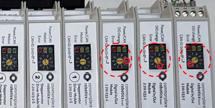
- Set the CAN ID with the selector on the front face:
- First (already existing) IO module: 0 (this results in CAN ID 0x70 = 112)
- Second (additional) IO module: 2 (this results in CAN ID 0x80 = 128)
- Third (additional) IO module: 4 (this results in CAN ID 0x90 = 144)
Electrical Integration
Digital Inputs
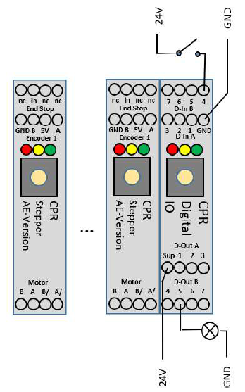
- Connect the ground pin (Output connector 1, to GND
- Supply 24V to one of the input pins
- Example on the left: 24V via switch to input pin 4
- Result in CPRog/iRC: digital input Din24 is triggered
Digital Outputs
- Connect the supply pin to 24V power supply
- The supply is forwarded to one of the outputs pins via reed relays
- Connect a valve or another component to the output pin
- Connect the component to GND to close the electrical circuit
- See the example with the lamp on output 5 on the left.
- In CPRog:
- Reset and Enable the robot
- Set DOut 25 to true to switch on the lamp
Software Integration
- Connect CPRog/iRC to the robot control.
- Open the configuration by clicking File -> Configure Project -> I/Os
- In the DIN rail I/O section set the number of modules
- Optional: Name the inputs and outputs and set the reset and error states.
- Click Save project
- Wait for at least 30 seconds, then restart the robot control and reload the project in iRC

