Difference between revisions of "How to operate a vacuum gripper using CPRog and the Modular Control Electronics"
From Wiki
| Line 5: | Line 5: | ||
===Digital Outputs=== | ===Digital Outputs=== | ||
The digital outputs are at the bottom of the image on the left. | The digital outputs are at the bottom of the image on the left. | ||
| − | + | * Disconnect the robot and its control electronics from power. | |
*Connect a (external 24V) power supply to the D-out A SUP (see image on the left) | *Connect a (external 24V) power supply to the D-out A SUP (see image on the left) | ||
*The supply voltage can be output to the pins labeled DOut A 1-3 and D-out B 4-7. There are seven separate reed relays that do the switching. | *The supply voltage can be output to the pins labeled DOut A 1-3 and D-out B 4-7. There are seven separate reed relays that do the switching. | ||
Revision as of 14:58, 18 June 2018
In general all grippers are controlled via a DIO module on the DIN rail. Normally, even when no gripper has been supplied, the modular control electronics come with a single DIO module.
Electrical Integration
Digital Outputs
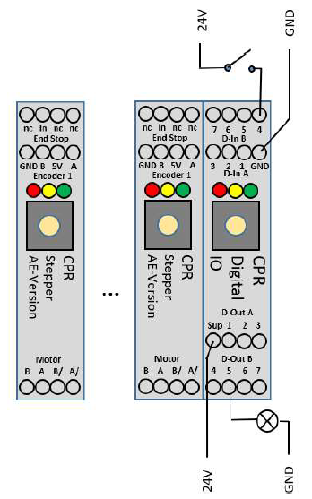
The digital outputs are at the bottom of the image on the left.
- Disconnect the robot and its control electronics from power.
- Connect a (external 24V) power supply to the D-out A SUP (see image on the left)
- The supply voltage can be output to the pins labeled DOut A 1-3 and D-out B 4-7. There are seven separate reed relays that do the switching.
- Depending on the gripper in use, connect the positive side of a solenoid valve or electrical gripper output pin. Here D-out B pin 5.
- Connect the negative side of the gripper to GND of the same power supply to close the electrical circuit.
- See the example with the lamp on output 5 on the left. (You would obviously connect the gripper in place of the lamp for the purpose of this tutorial.)
