How to operate a vacuum gripper using CPRog and the Modular Control Electronics
In general all grippers are controlled via a DIO module on the DIN rail. Normally, even when no gripper has been supplied, the Modular Control Electronics come with a single DIO module.
The DigitalIO module does not provide its own supply voltage. However the main supply of the Modular Control Electronics can be connected to the SUP pin (see section below) to supply power to the components connected to the digital outputs.
Electrical Integration
Digital Outputs
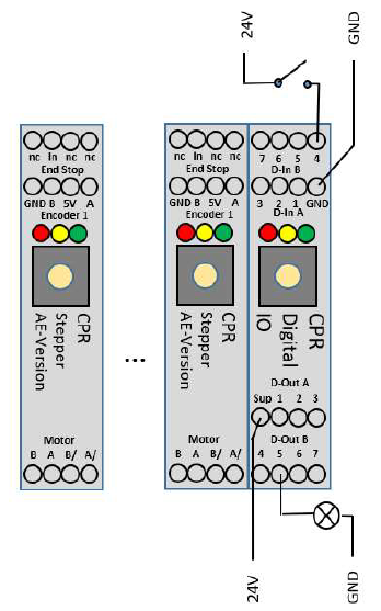
The digital outputs are at the bottom of the image on the left.
- Disconnect the robot and its control electronics from power.
- Connect a (external 24V) power supply to the D-out A "Sup" pin(see image on the left)
- The supply voltage can be output to the pins labeled DOut A "1-3" and D-out B "4-7". There are seven separate reed relays that close/open the connection between SUP and pin 1, 2, 3,...7 respectively.
- Depending on the gripper in use, connect the positive side of a solenoid valve or electrical gripper output pin. Here D-out B pin "5".
- Connect the negative side of the gripper to GND of the same power supply to close the electrical circuit.
- See the example with the lamp on output 5 on the left. (You would obviously connect the gripper in place of the lamp for the purpose of this tutorial.)
Note: The digital inputs at the top of the image on the left are irrelevant for the operation of the gripper. They demonstrate the use of digital Inputs and can remain disconnected for the purpose of this tutorial.
Operate the gripper in CPRog
This could also be titled "how to enable a digital output in CPRog".
- Turn on the power supply (or power supplies, when using a separate power supply for the gripper).
- Disengage the Emergency Stop button
- Start CPRog
- Connect, Reset, Enable
Manual Use
This is e.g. useful for an initial test: The tab "DIN-Rail Input/Output" in CPRog allows to check the input states and to set the output channels for up to three DIO modules. Note that there is also a tab simply called (Input/Output) this tab is not relevant for the modular control electronics. When the physical robot is connected, only the outputs can be set. The inputs are shown based on the signals from the electronics. (During simulation, i.e. with the physical robot disconnected, also the input channels can be set to simulate e.g. sensors.) Only the outputs are relevant for the gripper that we are trying to operate.
To operate the gripper connected to pin D-Out B "5" of the first DIO module, toggle the tick-box before "25: Dout" as shown on the screenshot below.
Use in CPRog Programs
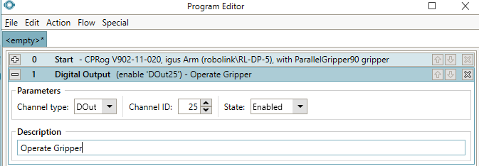
The same can be achieved in a CPRog program. To operate the gripper set DOut25 to true/false as shown in the image below.
This enables the
- fifth output of the first DIO module (DOut25)
Once you save, load and run the program the gripper should operate.
The program in this video closes the gripper once. You can see the activation of DOut25 at the bottom of the video around 39 seconds into the video. If the program is run multiple times, the gripper will stay closed. If you want to open the gripper again, add another Digital Out command in the same way and set the state of DOut25 to false. The program here is just running the simulation. When the robot is connected, reset and enabled, it will operate the physical robot in the same way.


