Difference between revisions of "How to operate an electrical parallel gripper using CPRog and the Modular Control Electronics"
From Wiki
| Line 18: | Line 18: | ||
*The pink lead is connected to the positive 24V rail. | *The pink lead is connected to the positive 24V rail. | ||
*The brown lead of the gripper is connected to the GND rail. | *The brown lead of the gripper is connected to the GND rail. | ||
| + | *A connection has to be made between the 24V rail and the DIO module "Sup" pin. | ||
Revision as of 09:54, 20 June 2018
Application
The PG01 is a timing-controlled, electrical parallel gripper. It is mainly used in educational applications and not suitable for manufacturing.
The Gripper operates on +24V DC supply voltage and 24V signal voltage.
- If the signal is high, the gripper motor will turn over for a set amount of time to open the jaws.
- If the signal is low, the gripper motor will turn over for a set amount of time to close the jaws.
After the gripper has closed a small holding current thrugh the motor will ensure that the gripper grips the object.
Mechanical Integration
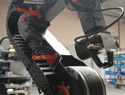
- The gripper is fixed with M4 screws to the flange of the robolink robot arm.
- The cable to the gripper has to be routed, so that it does not catch or get stuck during operation.
Elektrische connections
The gripper cable has to be routed via the cable ducts of the robolink robot and must be strain relieved.
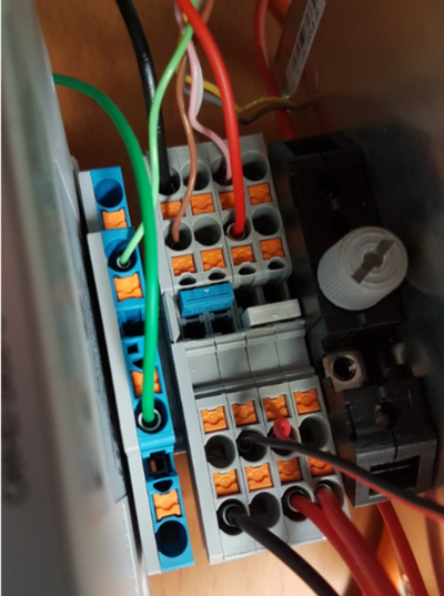
- The pink lead is connected to the positive 24V rail.
- The brown lead of the gripper is connected to the GND rail.
- A connection has to be made between the 24V rail and the DIO module "Sup" pin.

