Absolute Encoder Offset
All igus ReBeL robots are calibrated at the factory to reliably recognize the angle of each axis. The calibration consists of two parts, the calibration of the absolute encoder, at which encoder readouts are assigned angle values, and the offset, which moves the angle so that the 0 position of the joint is where it should be.
This article explains how to distinguish encoder issues and how to optimize the encoder offset. This should only be done if our support asks you to do this since wrong values will lead to positioning issues.
Issues and Symptoms
Please check the following to identify the issue and solution.
Calibration
Issues in the calibration lead to inconsistent positioning after re-referencing. E.g. the robot reliably reaches a position but after re-referencing (or restarting) it is off in position and/or orientation. Re-referencing may result in different position errors depending on the robot's pose during referencing. A workaround is using a referencing program. Recalibrating is only possible at the factory since the robot needs to be taken apart.
Test: Re-reference the robot at different poses. Is the position error constant or does it change? If it is constant check the offsets, if it changes contact support about the calibration.
Offsets
Issues in the offsets lead to an angular error for one or more joints. This causes issues reaching specific positions, distances or angles. Linear motions may be non-linear. The cartesian position error may depend on where you do your measurements, e.g. it may be bigger the further the position is from the robot's base.
Test: Move all joints to 0 and check whether all axes are in line. This may be tricky to measure, we suggest using a linear laser, a long ruler or spirit level. Make sure the ground that the robot is mounted to is horizontal.
Adapting the Encoder Offsets


You can adapt the encoder offsets of each joint via Module Control Closed Loop. Do this only if our support asks you to do it or if you are sure about the issue. Wrong values can cause severe positioning issues.
- Measure and note down the angle error of each joint as precise as possible. E.g. use iRC to move the robot into "candle" position, pointing straight up, then use a ruler or laser to fine tune each joint. Do this also for joints 1, 4 and 3 which may not be easy to measure. It may help to move a joint to 90° and check whether it is rectangular.
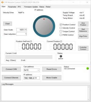
- Disconnect iRC, start Module Control Closed Loop. In the "Start" tab select a joint: Find the "Can address" box next to the connect buttons, 0x10 is A1, 0x20 is A2, 0x30 is A3, etc.
- Click "Connect Ethernet" to connect to the robot, then "Reset Errors" and "Motor Enable" to enable the joint.
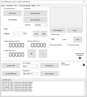
- Change to the "Rebel" tab. Important: Do NOT click any calibration related button, this can damage the encoder's calibration requiring you to send the robot back. The offset however can be easily restored if you got the original value. So make sure to click "read" in the "Offset" section and note the original offset of each joint.
- Now adapt the offset. Add or subtract your measured angle error to the offset value and click "Write". Note that the value of "Position Rebelencoder" below changes.
- Go back to the "Start" tab. Click "Start Reference" to update the current position with the new offset.
Do this for each joint. You can check the check with iRC between updating each joint or once all are done. If the errors got worse try subtracting instead of adding. If nothing helps restore the original values and contact support.