Changing Motor Currents
Both the motor torque and temperature are directly influenced by the current flowing through the motor. If your robot needs more torque you can try increasing the currents, if it overheats lower them. This article is a step-by-step guide on how to change motor currents.
Changing the motor currents requires the following steps:
- Load the amp configuration from the robot
- Open the file in a basic text editor
- Change the currents
- Write the configuration back to the robot
- Do a stress test to check the temperatures
Important Notes
Only change the currents if you really need to. The factory settings are chosen for reliability. Increasing the motor currents can damage or destroy components of your robot. Most robots only monitor the temperature of the electronics so it is your responsibility to check that the motors do not overheat.
Stepper motors have a maximum speed after which increasing the motor current has no effect other than increasing more heat. For further info on this effect read Torque Loss at High Velocities.
Do not increase the currents of ReBeL arms. This can lead to inconsistent positioning or melting components.
Load the Amp Configuration from the Robot

The motor current parameters are stored on the axis controllers, therefore they are not reset by a software update. These parameters are called firmware parameters or amp configuration, these terms are interchangable.
- Connect iRC / CPRog to the robot.
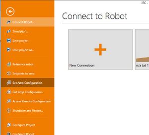
- Then click "File" → "Get Amp Configuration" to download the firmware parameters.
- iRC / CPRog will confirm that the parameters were loaded successfully and offer to open the directory to which the parameter file was written. Click "Open directory".
Open the Amp Configuration File
Find the newest file in the folder and open it in a basic text editor, e.g. Notepad. To do this do a right click on the file, then click "Edit". If some other program appears that is no text editor close it and do another right click on the file, then click "Open with" and select Notepad.
Change the Current Settings
The amp parameter file format differs between stepper controllers and BLDC / Closed Loop controllers, e.g. ReBeL arms and joints.
Stepper Axes
In the configuration file you will find one block like the following for each axis. Note that each block starts with <Joint0, <Joint1, <Joint2 etc. The counting starts at 0, so <Joint0 is axis 1, <Joint1 is axis 2 etc. External axes follow after the last robot axis.
 <Joint0 ID="16" Version="v02.20"
        ComTimeOut="2000" MaxCurrent="200" MaxLag="5000" EncoderErrorDetection="1000" PosP="1.000" PosI="0.0000" PosD="0.000" PosAWU="30"
        Encoder="True" SwapEncoderDirection="False" EndSwitchRising="True" StopOnEndSwitch="False" UseIndexAsRef="False" UseIniAndIndexAsRef="False"
        RefStraight="False" RefSinus="False" RefHalf="True" SinusRefTics="2000" SinusRefMaxCycles="6"
        Offset="502" RefSpeed="-50" RefSpeedSlow="-10" RefFromBothSides="True"
        SGThreshold="2" CSLoad="25" CSStart="22" CSIdle="5" CSRef="22" StartArea="200"
        MinSupplyVoltage="500" MaxTemperature="450" Microstepping="0"
       />
Find the four CS parameters CSLoad, CSStart, CSIdle and CSRef in the second to last line. These define the currents in different situations:
- CSLoad: current scale when moving
- CSStart: current scale at start of motion - usually equal to CSLoad
- CSIdle: current scale when not moving - keep this as low as possible to allow the motor to cool down when not in motion but high enough that axes do not drop down.
- CSRef: current scale when referencing - usually equal to CSLoad
The values of these parameters can be roughly translated to Amps, see article Motor Current Parameter. However, this is usually not relevant.
If you increase these values go in small steps (e.g. increase by 1 if < 10, increase by 1 or 2 if > 10), then load the parameters to the robot and test whether your torque requirements are met and make sure the motors and electronics do not overheat.
Save the file to a new name so that you can tell which file you changed.
BLDC / Closed Loop Axes
As explained above each axis is described by a block starting with <Joint0, <Joint1 etc where <Joint0 is axis 1, <Joint1 is axis 2 etc. Find the block for the axis that you want to change.
In that block find and change the following line. The value is in Milliamps.
<FWParameter Index="1" SubIndex="6" Name="max. current" Value="7500" Unit="mA" />
Write the Amp Configuration to the Robot
In iRC / CPRog click "File" -> "Set Amp Configuration" and select the changed file. This first creates a backup copy of the original parameters, then writes the new parameters. The current parameters become active immediately, changes to other parameters require a restart.
Test the changes
Do a stress test for 30-60 minutes to check whether your torque requirement is met and to make sure the electronics and the motors do not overheat. The axis modules are protected from overheating but the motors of most robots do not have temperature sensors. Check the motor temperatures with a thermometer or carefully by feeling.
If anything overheats stop immediately (e-stop) and lower the current parameters or return to the original values.