Difference between revisions of "Gantry axes moving in wrong direction"
(Created page with "When first setting up a gantry robot the axes may move in the wrong direction. Oftentimes this is caused by the mechanical setup differing from the intended setup but it can a...") |
m (Added configuration category) |
||
| Line 39: | Line 39: | ||
* Incorrect referencing offset. follow [[Swap_Axis_Direction#Referencing_Offset|Referencing Offset]] on how to fix this. | * Incorrect referencing offset. follow [[Swap_Axis_Direction#Referencing_Offset|Referencing Offset]] on how to fix this. | ||
| − | [[Category:CPRog]][[Category:TinyCtrl]] | + | [[Category:Configuration]][[Category:CPRog]][[Category:TinyCtrl]] |
Latest revision as of 16:39, 8 March 2023
When first setting up a gantry robot the axes may move in the wrong direction. Oftentimes this is caused by the mechanical setup differing from the intended setup but it can also have other reasons. This article explains how to troubleshoot this situation for a standard setup. Please read Swap Axis Direction if you need to change the axis direction for special configurations.
While the direction of the axes can be swapped via software configuration we recommend checking for mechanical reasons first. Otherwise a software update with new configuration can reset all changes and you might need to repeat this process.
The expected behavior
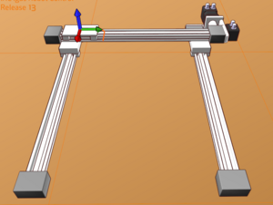
Start iRC and load the project for your type of gantry. If you did not do any changes to the configuration on your PC this simulation should look like the real gantry and show the intended behavior. If the X axis has two rails as shown on the right side the connecting rod should be at the far end. If you look at the gantry at this angle the zero position should be at the top left with the Z axis up.
In 3 axis gantries the first axis should move along the X axis, the second the Y axis and the third the Z axis. The Z axis is inverted, when axis 3 moves in positive direction in joint mode the cartesian Z value decreases, the physical axis moves down.
Fixing the motion direction
Jog motion direction
Before you try to reference the axis the general motion should be checked. Use the buttons in the "jogging" section at the bottom of iRC to move each axis and watch whether the physical axes move in the same direction. If iRC shows the position value being negative or larger than the allowed motion range the robot control will only allow motion in one direction. If parts of the gantry are not shown in iRC click "File" -> "Set axes to zero" to reset all axis positions.
The following reasons can cause the axis to move in the opposite direction:
- Axis mounted 180° rotated
- Motor mounted at the wrong side of the axis
- Mixed up wires at the motor electronic module in the control cabinet (this is unlikely, multiple wires need to be mixed up in the right way otherwise you would get an encoder error or unexpected motion behavior)
If you can rule out these mechanical factors you can change the motion direction in the software configuration as explained in section Motion Direction. Restart the robot control and check if the the axis moves in the correct direction.
Referencing direction
Once the axis jogs in the correct direction check the referencing. Keep the emergency stop nearby and start referencing an axis. The axis should first move towards the referencing switch at the zero position, then back a little and then move to the referencing switch at a slower speed and stop. After referencing iRC should show the position of the axis at or near 0.
The following reasons can cause the axis to move away from the referencing switch:
- Switch mounted at the wrong end of the axis
- Wrong type of referencing switch (opening/closing) or wrong signals. Watch the yellow LED at the corresponding motor module in the control cabinet. It should light up if and only if the carriage of the axis is at the switch. You can also hold a metal object like a screwdriver to the switch to test it. If the light is inverted you need to change parameter "EndSwitchRising" in the Firmware Parameter Configuration from True to False or the other way. If the LED is always on or always off check the wiring and try a different switch (e.g. temporarily connect one from a different axis) to check for a defect.
- If the switch works correctly change the referencing direction as explained in Referencing Direction.
Zero position
The 0 position should be at the position described earlier. The following reasons can cause it to be somewhere else:
- Referencing switch mounted at the wrong position
- Incorrect referencing offset. follow Referencing Offset on how to fix this.
