Difference between revisions of "Motor Current Parameter"
(Preliminary article) |
|||
| (5 intermediate revisions by the same user not shown) | |||
| Line 8: | Line 8: | ||
'''IMPORTANT:''' Do a stress test (e.g. 1hr) after changing the current scale parameter and watch the temperature at the motor. Since the motors do not have temperature sensors the electronics only monitors the temperatures of the electronic modules. | '''IMPORTANT:''' Do a stress test (e.g. 1hr) after changing the current scale parameter and watch the temperature at the motor. Since the motors do not have temperature sensors the electronics only monitors the temperatures of the electronic modules. | ||
| + | |||
| + | __TOC__ | ||
= Current Scale and Actual Current = | = Current Scale and Actual Current = | ||
| Line 55: | Line 57: | ||
{| class="wikitable" style="margin:auto" | {| class="wikitable" style="margin:auto" | ||
|- | |- | ||
| − | ! Motor | + | ! Motor !! Current Scale !! Actual Current |
|- | |- | ||
| − | | NEMA17 || | + | | NEMA17 || 8 || 1.9A |
|- | |- | ||
| − | | NEMA24 | + | | NEMA24 || 19 || 4.2A |
|} | |} | ||
| + | |||
| + | At low RPM the generated torque does not depend on voltage, a higher voltage delays the effects of back EMF and allows faster motion. Therefore the recommended current scale values are equal for both 24V and 48V systems. However, since a higher voltage creates more heat in the motor control electronics the current scale may need to be limited. | ||
Examples: | Examples: | ||
| Line 67: | Line 71: | ||
! Robot Type !! Motor !! Voltage !! Current Scale !! Actual Current | ! Robot Type !! Motor !! Voltage !! Current Scale !! Actual Current | ||
|- | |- | ||
| − | | DLE-RG-0014 || | + | | DLE-RG-0014 || NEMA24 || 24V || 25 || 5.4A |
|- | |- | ||
| || || 48V || 16 || 3.6A | | || || 48V || 16 || 3.6A | ||
| Line 85: | Line 89: | ||
= Torque Loss at High Velocities = | = Torque Loss at High Velocities = | ||
| − | The available torque of stepper motors decreases after a certain speed. This is an effect of Back EMF: the motor induces a current that is opposed to the current that turns the motor. The following diagram shows this effect; the usable current drops after 300 RPM. | + | The available torque of stepper motors decreases after a certain speed. This is an effect of Back EMF: the motor induces a current that is opposed to the current that turns the motor, decreasing the effective current. The following diagram shows this effect; the usable current drops after 300 RPM in a 48V system. This can cause issues like motor stalls at the fastest part of a motion. |
[[File:BackEMFVelocity.png|750px]] | [[File:BackEMFVelocity.png|750px]] | ||
| − | These effects are considered in construction where motors and | + | In 24V systems these effects start at even lower speeds as the following diagram shows. |
| + | |||
| + | [[File:BackEMFComparison.png|750px]] | ||
| + | |||
| + | These effects are considered in construction where motors, gears and voltage must be chosen for the appropriate speed range. | ||
[[Category:Configuration]] | [[Category:Configuration]] | ||
Latest revision as of 11:33, 24 June 2024
The motor current of stepper motors can be adapted to the requirements of each axis via the current scale parameters in the Firmware Parameter Configuration. The most important factors are required torque, motor size and generated heat: If the current is set too high or if the motor does too few cooling breaks with lower current the motor and electronics can overheat and get damaged.
The following current parameters can be configured:
- CSLoad: current scale under load conditions
- CSStart: current scale at start of motion
- CSIdle: current scale when not moving
- CSRef: current scale when referencing
IMPORTANT: Do a stress test (e.g. 1hr) after changing the current scale parameter and watch the temperature at the motor. Since the motors do not have temperature sensors the electronics only monitors the temperatures of the electronic modules.
Current Scale and Actual Current
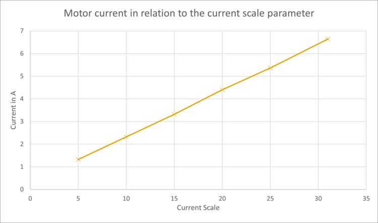
The current scale parameter is a number 1-31 that translates to a current as the following measurements show. This is independent from motor size and voltage.

| Current Scale | Actual Current (A) | Current Scale | Actual Current (A) |
|---|---|---|---|
| 1 | 0.5 | 16 | 3.6 |
| 2 | 0.7 | 17 | 3.8 |
| 3 | 0.9 | 18 | 4.0 |
| 4 | 1.1 | 19 | 4.2 |
| 5 | 1.3 | 20 | 4.4 |
| 6 | 1.5 | 21 | 4.6 |
| 7 | 1.7 | 22 | 4.8 |
| 8 | 1.9 | 23 | 5.0 |
| 9 | 2.1 | 24 | 5.2 |
| 10 | 2.3 | 25 | 5.4 |
| 11 | 2.5 | 26 | 5.6 |
| 12 | 2.7 | 27 | 5.8 |
| 13 | 2.9 | 28 | 6.0 |
| 14 | 3.1 | 29 | 6.2 |
| 15 | 3.3 | 30 | 6.4 |
| 31 | 6.6 |
Recommended Current Scale
We recommend the following values for the different motor types:
| Motor | Current Scale | Actual Current |
|---|---|---|
| NEMA17 | 8 | 1.9A |
| NEMA24 | 19 | 4.2A |
At low RPM the generated torque does not depend on voltage, a higher voltage delays the effects of back EMF and allows faster motion. Therefore the recommended current scale values are equal for both 24V and 48V systems. However, since a higher voltage creates more heat in the motor control electronics the current scale may need to be limited.
Examples:
| Robot Type | Motor | Voltage | Current Scale | Actual Current |
|---|---|---|---|---|
| DLE-RG-0014 | NEMA24 | 24V | 25 | 5.4A |
| 48V | 16 | 3.6A | ||
| NEMA23 | 24V | 22 | 4.8A | |
| 48V | 15 | 3.3A | ||
| NEMA17 | 24V | 12 | 2.7A | |
| 48V | 6 | 1.5A | ||
| DLE-RG-0374 | NEMA23 | 24V | 25 | 5.4A |
| 48V | 16 | 3.6A |
Torque Loss at High Velocities
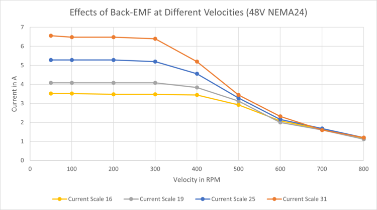
The available torque of stepper motors decreases after a certain speed. This is an effect of Back EMF: the motor induces a current that is opposed to the current that turns the motor, decreasing the effective current. The following diagram shows this effect; the usable current drops after 300 RPM in a 48V system. This can cause issues like motor stalls at the fastest part of a motion.
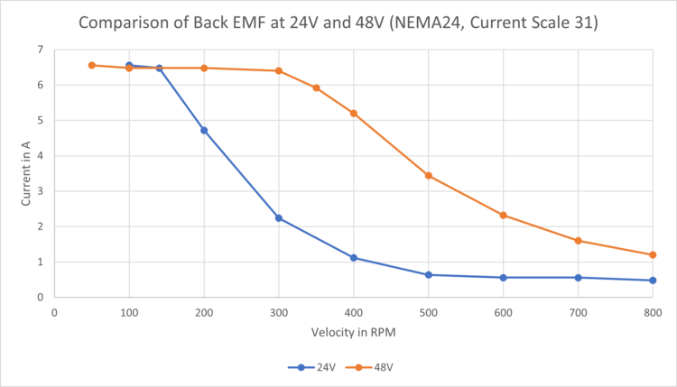
In 24V systems these effects start at even lower speeds as the following diagram shows.
These effects are considered in construction where motors, gears and voltage must be chosen for the appropriate speed range.

