Difference between revisions of "Digital Inputs / Outputs"
| Line 47: | Line 47: | ||
==How to use the inputs== | ==How to use the inputs== | ||
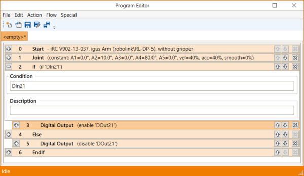
| − | [[file:DIO_cprog_input_program.png|thumb|600px|right]] | + | [[file:DIO_cprog_input_program.png|thumb|600px|right|Check status of Digital Input in an if-statement ]] |
The digital inputs can be used e.g. in if-then-else statements. | The digital inputs can be used e.g. in if-then-else statements. | ||
The '''example''' program on the right shows a simple test. The first input of the first DIO module (DIn21) is checked. If it is true than the first output of the first DIO module (DOut21) is set. | The '''example''' program on the right shows a simple test. The first input of the first DIO module (DIn21) is checked. If it is true than the first output of the first DIO module (DOut21) is set. | ||
[[Category:CPRog]][[Category:robolink]] | [[Category:CPRog]][[Category:robolink]] | ||
Revision as of 16:32, 18 June 2018
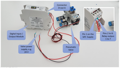
The CPR robolink control electronics come with a digital input / output module. This page shows how to connect actuators, valves or sensors to the module.
The Digital IO module provides 7 digital inputs and 7 digital outputs. The inputs are electrically decoupled from the control electronics by an optocoupler and accept 24V input signals. The outputs are reed relays which can drive up to 500 mA per channel.
Indicators: When the state of a sensor input or and output changes the orange LED on the top is blinking once.
CPRog project configuration
Each robot control is shipped configured for a single Digital IO module as standard. So if you have only one Digital IO module, skip this section.
If you want to add an additional module, please add a line in the project file for your robot, e.g. C:\CPRog\Data\Project\51_IGUS_arm5DOF_SV.prj:
You can see which project file is currently in use in the title bar of CPRog, while the CPRog window is not maximised to fill the screen. (In general, the correct project configuration file for a given robot can be found like this.)
<DIOModule ID="112"/>
<span style="color:#008000"><DIOModule ID="128"/></span>
The first line shows the existing entry for the first Digital IO module (CAN ID 112 = 0x70). The ID switch at the top of this physical module is set to 1.
The second line adds a Digital IO module with CAN ID 128 = 0x80. The ID switch on the physical module has to be set to 2 to match this ID.
Nomenclature
To control the IOs in Software, all CPR robots provide digital inputs and outputs are named channel 1 through 4.
This should get clearer as you read the "How to use the inputs" and "How to use the outputs" paragraphs.
In contrast, the igus robolink arms and gantry robots use the following nomenclature:
- For the first DIO-Modul: Channels 21 through 27, i.e. Ch: 21, Ch: 22,...
- For the second DIO-Modul: Channels 31 through 37
- For the third DIO-Modul: Channels 41 through 47
The maximum amount of DIO modules installed in the control electronics is currently 3.
Attention: The DIO are also used by the PLC Interface (if active), refer to this.
How to use the outputs
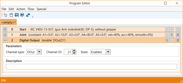
The output signals can be switched on or off with the 'Digital Out' command in CPRog (see screenshot on the right).
Please be aware that the outputs can only be switched on when the robot is enabled!
![]() The outputs must not drive more then 500 mA, also not at startup! Avoid higher currents, e.g. caused by the inrush current of capacitors! Use a secondary relay in this case to prevent damage to the DIO module.
The outputs must not drive more then 500 mA, also not at startup! Avoid higher currents, e.g. caused by the inrush current of capacitors! Use a secondary relay in this case to prevent damage to the DIO module.
Here an example on How to operate a gripper using CPRog and the Modular Control Electronics
How to use the inputs
The digital inputs can be used e.g. in if-then-else statements.
The example program on the right shows a simple test. The first input of the first DIO module (DIn21) is checked. If it is true than the first output of the first DIO module (DOut21) is set.


