Difference between revisions of "2D Camera Integration"
| Line 106: | Line 106: | ||
===Camera Configuration=== | ===Camera Configuration=== | ||
| − | * This is the place where the IP-Address of the camera, which has been | + | * This is the place where the IP-Address of the camera, which has been left at the default setting earlier in this how-to (192.168.0.49), has to be entered. |
| − | + | * The default settings in this configuration window are identical to the IFM defaults. | |
| − | IFM | + | |
| − | + | * Pixel-to-coordinate-conversion: The camera outputs the object position results in pixels and hands it over to the plugin. To calculate the robot target position the pixel values have to be multiplied with the scaling factor. The scaling factor is dependent on the distance between camera and the surface the camera looks at (see next section). | |
| − | + | ||
| − | + | * Geometry Setup: The position of the camera has to be defined relative to the robot. This is necessary to transfer the target position (in camera pixels) into an absolute position in the robot coordinate system. | |
| − | + | ||
| − | + | * Origin: The nposition of the camera in the robot coordinate system (x/y/z value). | |
| − | + | ||
| − | Geometry Setup | + | * Look Vec(tor): The vieweing direction of the camera. In the image above, the camera looks down onto the work surface that the robot sits on, hence it looks in negative Z direction. |
| − | + | * Up Vec(tor): This vector defines the rotation of the camera around the target axis, i.e. top and bottom in a 2D image. | |
| − | + | * Pick Distance: Is the distance between the top of the work-piece and the camera. | |
| − | + | ||
| − | + | *Example: Work-piece located in the center below the camera would produce a target position (120, 120, 35) | |
| − | Origin: | + | |
| − | + | *Test Configuration: For testing purposes the plugin can be configured so that it produces a target position, even when the camera is disconnected. This is so that a program can be tested in simulation mode: When the tick before "Override Camera" is set target position and model class defined in the line below is returned by the plugin. | |
| − | Look Vec: | + | *Status: Here the status of the camera connected is shown, i.e. the connection status and the current target position in pixels and mm. |
| − | + | ||
| − | + | * The apply any changes made in this window, the "Update" button needs to be clicked. The changes will then be uploaded to the camera and also saved in the camera configuration file, so that they are not lost after restart. | |
| − | Up Vec: | + | |
| − | + | ===Status=== | |
| − | + | During operation the values that the plugin returns (position and model type) can be checked in the in the "variables" tab at the bottom of CPRog. | |
| − | Pick Distance: | + | [[file:IFM_plugin_status_cprog.png]] |
| − | |||
| − | |||
| − | |||
| − | |||
| − | Test Configuration | ||
| − | |||
| − | |||
| − | |||
| − | |||
| − | |||
| − | Status | ||
| − | |||
| − | |||
| − | |||
| − | |||
[[Category:CPRog]][[Category:CPRog Plugins]] | [[Category:CPRog]][[Category:CPRog Plugins]] | ||
Revision as of 12:36, 3 December 2018
Different cameras can be integrated in the CPRog software. This allows to pick parts with a not precisely defined position.
Currently plugins are available for:
- IFM O2D, a compact camera with integrated image processing
- Matrox camera systems
Both systems aquire an image and process it internally. Then they send the target position via Ethernet to the CPRog software. Here they are received by an plugin and stored in a variable. This variable can be used in a motion.
A more in-depth explanation and an example program can be found in the documentation (german): Dokumentation_PlugIn_IFM-O2D_V03.pdf (DE) The english version of that same documentation is being worked on at the moment.
UNDER CONSTRUCTION. Currently the English translation of the documentation linked above is being generated
Scope
This document explains the use of an IFM 3D camera in CPRog.
Safety
 Caution! Personal safety has to be ensured during operation.
 This is especially relevant during configuration and set up of the camera application. All motion has to be carried out at slow speeds.
 The operator has to be ready to stop the robot
 It is recommanded that all programs are tested in the simulation prior to moving the robot.
Mechanical and electrical setup
The camera has to be mounted at ample height above the work-pieces. Care has to be taken to avoid any collisions. For acceptance cone and minimum distance from camera, please look at the IFM-Documentation.
- The camera should be mounted parallel to the coordinate axes of the robot, if at all possible. - That means either overhead, in front or from the side. This will simplify calibration significantly (see image on the right).
- Power requirements: Connect the leads of the black power cable to a 24V supply:
- blue lead: GND
- brown lead: 24V (bitte verifizieren Sie die Belegung mit der IFM-Dokumentation).
- Plug ethernet cable into camera and PC.
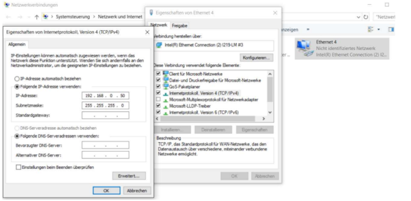
- Set IP of PC to a free IP in the
192.168.0/24range, e.g.192.168.0.50 - Camera IP is factory configured for
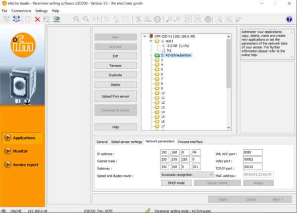
192.168.0.49
Camera configuration
The image processing is done entirely in camera. To recognize a work-piece an "application" has to be set up containing the model of the work-piece. The camera settings are configured using the IFM Software efector dualis E2D200.
Communication with the CPRog-Plugin requires the following settings:
- General TCP/IP settings: The TCP/IP address and port configuration have to remain the IFM factory defaults.
- The Protocol Version has to remain in the factory default setting.
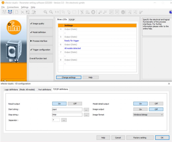
- Click on "Process Interface" and "Change Settings". The window "IO configuration" appears.
- In the "TCP/IP settings" set
- "Result Output" to On
- "Model Detail Output" to On
Plugin Installation in CPRog
A plugin is used to use the IFM camera. It connects via ethernet to the camera and translates and transmits the data received from the camera to the robot control electronics.
Save the following files to C:\CPRog\Data\Plugins\
That's it.
An example program (Example_IFM_Camera.xml) can be saved to C:\CPRog\Data\Programs\
Use of the plugin within a robot program
Three commands have to be inserted in the Program editor to get the camera up and running. These commands can be added via the menu item "Advanced Commands"
- In the first line a position variable is defined. This variable is used to store the target position in.
- in the second line a Number variable is defined. This variable is used to store the model type in. Once the camera has recognized an object it is set to
-1. - The command "PlugInTargetPos" calls a plugin that returns a target position. It takes the following arguments
- Name of the plugin to be used (here "PluginSmartCameraIFMO2D").
- a variable for the target position
- a variable for the model type.
- The plugin overwrites only the X, Y, Z and A (=rotation around Z) values. The rotation values B and C remain as they were. Therefore, upon definition of the variable the robot should already have been positioned so that it can grip the object with the current B and C values.
The example program uses the plugin. It moves the robot to a starting position and asks the plugin for a target position.

When the variable "modelclassvar" becomes -1 a small up and down movement is carried out.
Otherwise the robot will move to the target position by using the command "LinearByVariable".
First Run/Configuration
In general, a new program should always be run in simulation prior to using it on the actual robot. To run the program in simulation simply click the plug button in CPRog to disconnect the robot. As soon as the Status light in CPRog changes (from red or green) to grey, you are in simulation mode.
When running the program for the first time, the plugin configuration window opens. Keep it open. Here the camera position needs be configured. File:IFM camera config.png
Camera Configuration
- This is the place where the IP-Address of the camera, which has been left at the default setting earlier in this how-to (192.168.0.49), has to be entered.
- The default settings in this configuration window are identical to the IFM defaults.
- Pixel-to-coordinate-conversion: The camera outputs the object position results in pixels and hands it over to the plugin. To calculate the robot target position the pixel values have to be multiplied with the scaling factor. The scaling factor is dependent on the distance between camera and the surface the camera looks at (see next section).
- Geometry Setup: The position of the camera has to be defined relative to the robot. This is necessary to transfer the target position (in camera pixels) into an absolute position in the robot coordinate system.
- Origin: The nposition of the camera in the robot coordinate system (x/y/z value).
- Look Vec(tor): The vieweing direction of the camera. In the image above, the camera looks down onto the work surface that the robot sits on, hence it looks in negative Z direction.
- Up Vec(tor): This vector defines the rotation of the camera around the target axis, i.e. top and bottom in a 2D image.
- Pick Distance: Is the distance between the top of the work-piece and the camera.
- Example: Work-piece located in the center below the camera would produce a target position (120, 120, 35)
- Test Configuration: For testing purposes the plugin can be configured so that it produces a target position, even when the camera is disconnected. This is so that a program can be tested in simulation mode: When the tick before "Override Camera" is set target position and model class defined in the line below is returned by the plugin.
- Status: Here the status of the camera connected is shown, i.e. the connection status and the current target position in pixels and mm.
- The apply any changes made in this window, the "Update" button needs to be clicked. The changes will then be uploaded to the camera and also saved in the camera configuration file, so that they are not lost after restart.
Status
During operation the values that the plugin returns (position and model type) can be checked in the in the "variables" tab at the bottom of CPRog. File:IFM plugin status cprog.png


