Difference between revisions of "Circular Motion"
(Rewrite of teach-in and calculation) |
m |
||
| Line 65: | Line 65: | ||
This package contains example programs that show how the circular motion command can be used: [[File:CircularMotionExamples.zip]]. You can run them in the iRC simulation. | This package contains example programs that show how the circular motion command can be used: [[File:CircularMotionExamples.zip]]. You can run them in the iRC simulation. | ||
| − | [[Category:CPRog]][[Category:TinyCtrl]] | + | [[Category:CPRog]][[Category:Robot Programming]][[Category:TinyCtrl]] |
Revision as of 13:16, 21 June 2024
The circular motion command can be used to define curved paths. It is supported from CPRog/iRC and TinyCtrl V13. This article gives a short introduction and hints on how to define curves.
Defining a Circular Motion
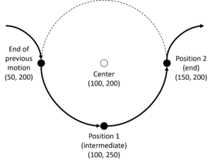
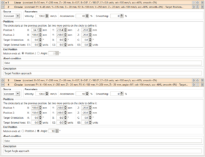
A circular path is defined by three points on a circle, as shown in the diagram. The starting point is defined by the target position of the previous motion command. Positions 1 and 2 are arbitrary points on the circle. The parameter "Motion ends at" defines whether the circle is left at point 2 or after a certain angle. The angle can be before or after point 2. It is also possible to circle several times (angle greater than 360°) or move in the opposite direction (negative angle).
If the tool is to be rotated during the circular movement, the target orientation can be specified. The angles from the start orientation to the target orientation are interpolated linearly. If specified, the positions of the external axes are also calculated.
The positions can be defined as constants or via variables and are relative to the given user frame.
Teach-In
If you got a circular curve under your robot the easiest way is to program by teach-in:
- Move the robot to the start position of the curve and add a linear instruction.
- Move the robot to any position on the curve, e.g. half way. Add the circle instruction.
- Move the robot to the end of the curve and click the "Set current position" button in the "Position 2" line.
- Optional: click the "Set Current Ori + Ext" button if the tool orientation or external axes change during the curve path.
Circle in a plane
If your circle is aligned to the coordinate axes calculating the positions is very easy.
Refer to the diagram above, you may want to do a similar sketch. First calculate the center position and radius. Add/subtract the radius from the X,Y and/or Z values of the center to get 3 points on the circle. One of them should be the starting position, set this as the target of the previous command. Set the other two as positions 1 and 2 of the circular command (the robot will move via 1 to 2).
Even if you do not want to move 180°, it is often easiest to use positions 1 and 2 at 0°, 90°, 180° or 270° and to specify the actual angle to be moved using the end of movement parameter. This allows the positions to be calculated as described above without trigonometry.
Calculating the example values in the diagram can be done like this:
- Center: X=100, Y=200, Z=any value (since this circle is in the XY plane), radius: 50mm
- Start position towards negative X: subtract radius from X: X=50, Y=200
- Position 1 (intermediate position): add radius from Y: X=100, Y=250 (you can subtract instead if you want to move in the opposite direction)
- Position 2 (end position): add radius to X: X=150, Y=200
The same approach works if the circle were in a different plane.
Complex circles
For more complex circles, e.g. circles that are in a tilted plane or whose starting point is not on a X/Y/Z line to the center point, may need some trigonometric calculations or measuring from a good sketch.
Tool Orientation and External Axes
To rotate the tool enter the target orientation, the value is linearly interpolated over the entire motion. Warning: The robot kinematic will choose the shortest rotation direction. This may lead to joint limit errors or the direction swapping if the rotation is 180° or more. In this case you may need to split the circle into multiple partial motions.
To move external axes enter their target positions, the value is linearly interpolated over the entire motion
Variable Positions
The positions can be defined as constants or via variables. The latter can be used to dynamically define the path by camera or PLC data. Please keep the hints above on variable positions and orientations in mind and test your program well.
The circular command uses 2 variables. One defines position 1 only, the other defines position 2, as well as the target orientation and external axes.
Smoothing and Combined Paths
The circular motion is compatible to the linear motion so that a combined path without stops can be defined. Smoothing can be used to smooth discontinuities between commands. E.g. if a circular curve is followed by a linear motion or another curve and the commands are not perfectly aligned smoothing will cut some distance off each motion command and add a smooth curve inbetween. A higher value of the smoothing parameter will cut more, which can lead to the circular and linear path being followed less precisely. A value of 0 will disable smoothing, in this case the robot will shortly stop before continuing the next command.
Hint: Use a low smoothing value of e.g. 1% to avoid stopping while keeping the motion precise.
Please note: Smoothing is limited by the value of the "LookAhead" parameter in the robot configuration. This means that after X succeeding commands the smoothing will ignored for one command. If you define a long path you may notice this as the robot stopping each X commands.
Example Programs
This package contains example programs that show how the circular motion command can be used: File:CircularMotionExamples.zip. You can run them in the iRC simulation.

