Definition of a DXF file in SolidWorks
This example shows how to define a dxf glueing path with the SolidWorks CAD software
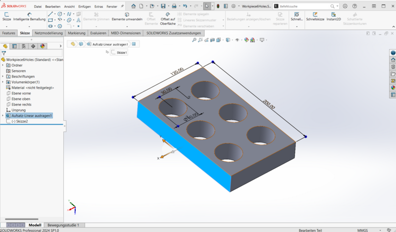
In the following picture you can see an example workpiece, a rectangular shape with six holes. Glue has to be applied before the next assembly step with 2 mm distance to the outer edges and the holes.
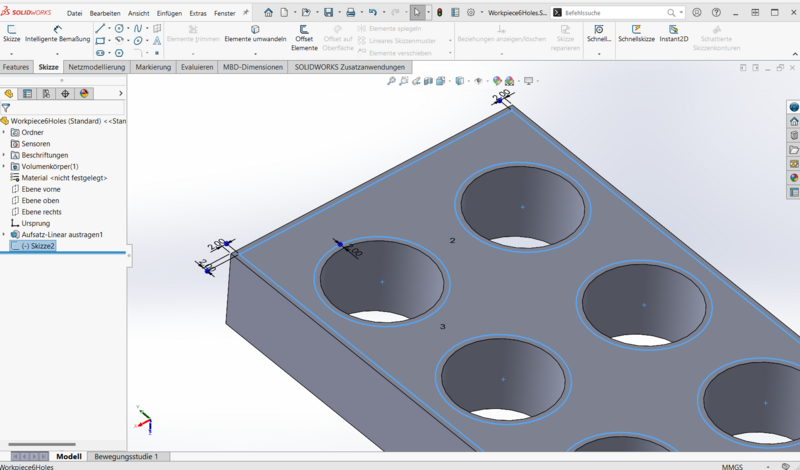
The next screen show the gluing path as a sketch defined based on the features or the original workpiece.
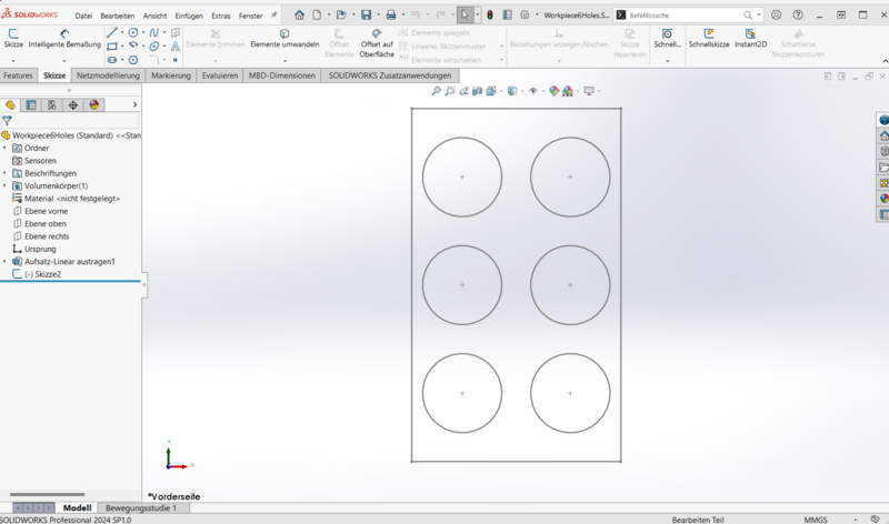
To export the gluing path you need to be in a top view above the workpiece and you have to set all solids and sketches besides the glueing sktech to invisible.
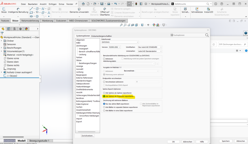
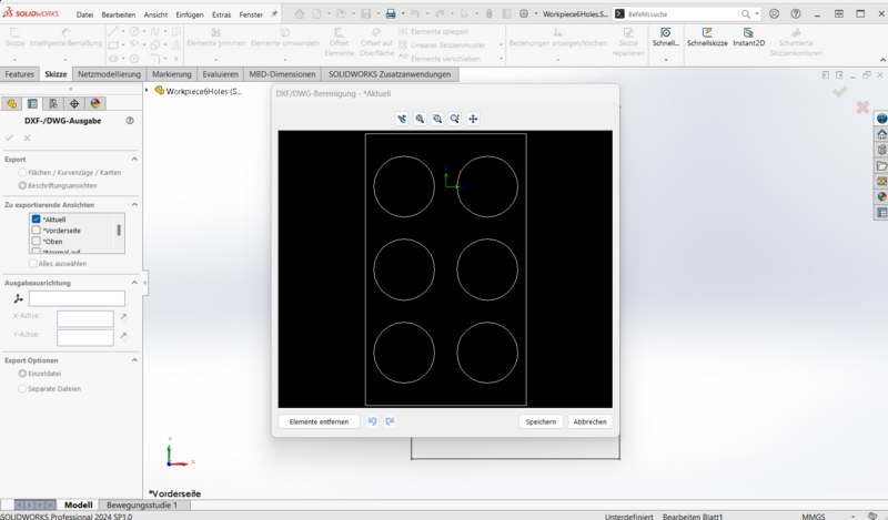
To be readable for the iRC splines have to be exported as polylines. Please also set the export dimension to mm. If you want to have a specific position of the path relative to the zero position of the robot you can define a reference coordinate system and choose it here as export reference.
Please check the export screen that all of your desired glueing path are included, but no other elements.
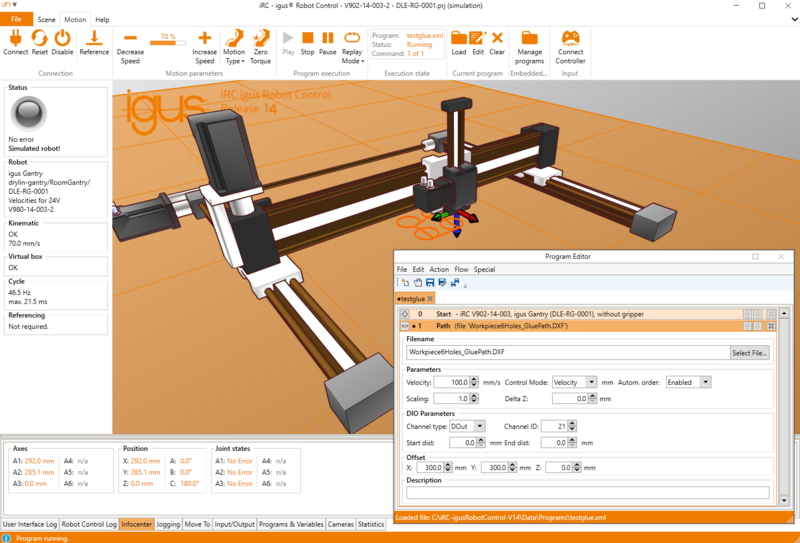
Loaded in the iRC you can replay the path.
