Difference between revisions of "2D Camera Integration"
(Added more hints to the calibration section) |
|||
| (33 intermediate revisions by 3 users not shown) | |||
| Line 1: | Line 1: | ||
| − | + | The robot control supports object recognition and video cameras. Object recognition cameras are used to detect object types and positions relative to the robot while video cameras provide images for observing the robot. | |
| − | Currently | + | Currently the following cameras are supported: |
| − | * | + | * ifm O2D200 and O2D500 object recognition cameras |
| − | * | + | * [[Remote_Variable_Access#Protocol|Cameras that can send TCP/IP messages in the same format as the O2D]] |
| + | * USB video cameras - these do not provide object info or positions! | ||
| − | + | This article explains how to set up the O2D200 and O2D500 cameras. [https://youtu.be/OJcislaY9Ek There also is a video (in German) that shows the entire process for the ifm O2D200]. | |
| − | |||
| − | |||
| − | |||
| − | |||
| − | |||
| − | |||
| − | |||
| − | |||
| − | |||
| − | |||
| − | |||
| − | |||
| − | |||
| − | |||
| − | |||
=Safety= | =Safety= | ||
* [[file:Caution.png|20px]] Caution! Personal safety has to be ensured during operation. | * [[file:Caution.png|20px]] Caution! Personal safety has to be ensured during operation. | ||
| Line 30: | Line 16: | ||
=Mechanical and electrical setup= | =Mechanical and electrical setup= | ||
[[file:IFM_camera_vectors.png|thumb|right|600px|Preferred camera mounting position]] | [[file:IFM_camera_vectors.png|thumb|right|600px|Preferred camera mounting position]] | ||
| − | + | Please refer to the camera's documentation on how to integrate it. | |
| − | *The camera should be mounted parallel to the coordinate axes of the robot | + | *Be careful to avoid collisions by the robot. |
| + | *Consider the acceptance cone and minimum distance of the camera. | ||
| + | *The camera should be mounted parallel to the coordinate axes of the robot if possible. - That means either overhead, in front or from the side at an angle of 0°, 90° or 180°. This will simplify calibration significantly (see image on the right). | ||
| − | + | =Camera configuration= | |
| − | + | The ifm O2D200 and O2D500 cameras use different tools for configuring the camera. The following sections only show a step by step summary, please read the camera's documentation for further info. | |
| − | |||
| − | |||
| − | = | + | == ifm O2D200 == |
| − | [[file: | + | [[file:IFM_camera_configuration_E2D200.png|thumb|right|600px|IFM Camera TCP/IP setings]] |
| − | |||
| − | |||
| − | |||
| − | |||
| − | + | The image processing is done entirely in camera. To recognize a workpiece an "application" has to be set up containing the model of the workpiece. The camera is configured using the IFM Software efector dualis E2D200. | |
| − | |||
| − | + | Communication with the robot control requires the following settings: | |
| + | * TCP/IP settings: | ||
| + | ** Without embedded control: Keep the factory defaul IP address or use one of your choice in the network of your computer. | ||
| + | ** With Raspberry Pi-based embedded control: 192.168.3.49 or a different address in that same network but not 192.168.3.11. Since this ethernet port is used for connecting the computer you may need to use a network switch so you can connect both. | ||
| + | ** With Phytec-based embedded control: | ||
| + | *** Ethernet port 2 (recommended): 192.168.4.49 or a different address in that same network but not 192.168.4.11. | ||
| + | *** Ethernet port 1: See Raspberry Pi-based control. | ||
| + | After changing the IP address you may need to update the IP address of your computer as described in section [[2D_Camera_Integration#PC Network Configuration|PC Network Configuration]] otherwise you may not be able to connect to the camera. | ||
| − | |||
| − | |||
* An [[media:TestConfig_IFM-O2D_CPR.zip|example camera configuration]] can be downloaded here - it is set up to recognize a 2 Euro coin in our lighting conditions and camera set up. (Your mileage may vary. This file is provided to make sure that parameters, such as IP and result output are correct.) To get it to actually recognize a coin, read the IFM documentation. The file has to be unzipped before loading it by right clicking on an unused folder in the "Applications" dialogue and selecting "Download to Sensor" followed by right clicking on the same folder and selecting "Activate". Not that the IP configuration of the camera is also updated (to the defaultsettings) when doing that (192.168.0.49). | * An [[media:TestConfig_IFM-O2D_CPR.zip|example camera configuration]] can be downloaded here - it is set up to recognize a 2 Euro coin in our lighting conditions and camera set up. (Your mileage may vary. This file is provided to make sure that parameters, such as IP and result output are correct.) To get it to actually recognize a coin, read the IFM documentation. The file has to be unzipped before loading it by right clicking on an unused folder in the "Applications" dialogue and selecting "Download to Sensor" followed by right clicking on the same folder and selecting "Activate". Not that the IP configuration of the camera is also updated (to the defaultsettings) when doing that (192.168.0.49). | ||
| − | |||
| − | |||
<br clear=all> | <br clear=all> | ||
[[file:IFM_camera_configuration_E2D200_1.png|thumb|right|600px|IFM Protocol Version settings]] | [[file:IFM_camera_configuration_E2D200_1.png|thumb|right|600px|IFM Protocol Version settings]] | ||
| − | *The Protocol Version | + | *The Protocol Version must be V2 and the output format ASCII. |
<br clear=all> | <br clear=all> | ||
| Line 68: | Line 52: | ||
** "Result Output" to On | ** "Result Output" to On | ||
** "Model Detail Output" to On | ** "Model Detail Output" to On | ||
| + | ** "Start sring" to "start" | ||
| + | ** "Stop string" to "stop" | ||
| + | ** "Separator" tp "#" | ||
| + | ** "Image output" may be On or Off. Set this to "On" if you want to be able to see the camera's image in CPRog/iRC, otherwise "Off" is recommended | ||
| + | ** "Image format" to "Windows bitmap" | ||
| + | <br clear=all> | ||
| − | + | Make sure that the camera recognizes your object reliably enough before proceeding to the next step: [[2D_Camera_Integration#Setting_up_the_Robot_Control|Setting up the Robot Control]]. | |
| + | |||
| + | == ifm O2D500 == | ||
| + | The ifm O2D500 provides different operating modes, two of which are supported by our robot control: | ||
| + | * Contour presence control | ||
| + | * Advanced application | ||
| + | |||
| + | By default contour presence control does not send object IDs. This may be relevant if your robot needs to distinguish objects. An alternative communication preset can be loaded to include the object IDs. | ||
| − | + | '''Make sure you are using at least firmware version 1.27.9941''' (see the title bar of the ifm configuration tool after connecting to the camera). | |
| − | |||
| − | + | === Protocol === | |
| − | + | Make sure the process interface protocol is set to V3: Open Device Setup -> Interfaces and check the setting of "Process interface version". | |
| − | |||
| − | |||
| − | + | === Creating a Coutour Presence Control Application === | |
| + | The fastest way to set up a simple image recognition application is via the contour presence control assistant. Simply follow the steps as shown in the screenshots and enter the following settings: | ||
| + | * in step 2: Set trigger to continuous or process interface (request images via the "Trigger Camera" robot program command). | ||
| + | * in step 7: Hint: consider setting "Orientation" to -180 - 180 so that the object is recognized in any orientation. | ||
| + | * in step 8: Set output interface to Ethernet | ||
| + | * in step 9: Enable "Model result" and "ROI results", "Object results" is optional. Set "Start" to either "star" or "start", "Delimiter" to "#" and "End" to "stop" | ||
| − | + | <gallery> | |
| + | File:IfmO2D500CountourAssistantEN_00.png|Setting up contour presence control | ||
| + | File:IfmO2D500CountourAssistantEN_01.png|Step 1 | ||
| + | File:IfmO2D500CountourAssistantEN_02.png|Step 2 | ||
| + | File:IfmO2D500CountourAssistantEN_03.png|Step 3 | ||
| + | File:IfmO2D500CountourAssistantEN_04.png|Step 4 | ||
| + | File:IfmO2D500CountourAssistantEN_05.png|Step 5 | ||
| + | File:IfmO2D500CountourAssistantEN_06.png|Step 6 | ||
| + | File:IfmO2D500CountourAssistantEN_07.png|Step 7 | ||
| + | File:IfmO2D500CountourAssistantEN_08.png|Step 8 | ||
| + | File:IfmO2D500CountourAssistantEN_09.png|Step 9 | ||
| + | File:IfmO2D500CountourAssistantEN_11.png|Step 11 | ||
| + | </gallery> | ||
| − | = | + | ==== Coordinate Types ==== |
| − | |||
| − | |||
| − | + | By default the camera sends image coordinates (pixel positions) which then need to be transformed by the robot control, see section [[2D_Camera_Integration#Setting_up_the_Robot_Control|Setting up the Robot Control]] on how to do the calibration. Alternatively the camera can be calibrated to do the coordinate transformation and send positions relatively to the robot in mm: | |
| − | |||
| − | |||
| − | |||
| − | |||
| − | |||
| − | |||
| − | + | # Select your camera application and click "Edit application" below the "Application details" at the right side. | |
| − | + | # If asked choose to change to advanced configuration (you can't use the assistant for this application afterwards). | |
| + | # Open the "Images & trigger" configuration, then find "Calibration" button in the "Trigger & general" section. | ||
| + | # Follow the "Robot sensor calibration" wizard. Please refer to the camera's documentation if any issues occur. | ||
| − | + | The camera by default still sends the pixel position. To send the cartesian position you need to set the "Robot Coordinates" interface preset as explained in the next section. | |
| − | + | ==== Model ID and Interface Preset ==== | |
| − | + | By default the contour presence control mode does not send model IDs. If you need to distinguish objects change to an advanced application as described in the previous section. Then follow these steps: | |
| − | + | # Open the Interfaces configuration of your camera application | |
| + | # In the TCP/IP section check if the preset for igus robots is available. [[File:Ifm_O2D500_Presets_for_iRC.zip|Otherwise you can get it here]]. | ||
| + | # Select the preset for image coordinates unless you calibrated for robot coordinates and save the application. | ||
| − | + | === Creating an Advanced Application === | |
| + | Creating an advanced application may be the faster approach if you know what you're doing or if you want to define multiple objects. | ||
| − | + | # Create a new application and select advanced application. There is no wizard to follow. | |
| + | # Calibrate for robot coordinates as explained in the section "Coordinate Types" above. | ||
| + | # Load the interface preset as explained in the section "Model ID and Interface Preset" above. | ||
| + | # Define your models | ||
| + | # Save the application | ||
| − | |||
| − | |||
| − | + | =Setting up the Robot Control= | |
| + | [[File:Camera_Configuration.PNG|thumb|right|600px|Configuration in CPRog/iRC]] | ||
| − | + | Now that the camera is ready to deliver object model and position information the robot control needs to be set up to connect to the camera and calculate the object/pick positions in 3D space. | |
| − | * | + | * Start CPRog/iRC and connect it to the robot if you are using one with embedded control. |
| + | * Open the camera configuration: File -> Configure Interfaces -> Cameras | ||
| + | * Add a new camera of type "IFM O2D". | ||
| − | + | The configuration area should look similar to the screenshot on the right. | |
| − | |||
| − | |||
| − | + | '''Please note:''' If you change camera settings, e.g. your camera application, the robot may continue receiving values by the old configuration until reconnected. To do this simply click "Apply" in the interface configuration of CPRog/iRC. | |
| − | + | ===General Settings=== | |
| − | + | These settings refer to the connection to the camera and enable it to be used in a robot program. | |
| − | * | + | * '''Enabled''': This enables the camera in CPRog/iRC. If disabled the values from the simulation section will be used. Keep this disabled if you are using an embedded control, otherwise CPRog/iRC might prevent the embedded control from receiving data from the camera. |
| + | * '''Image enabled''': If an image is received it will be shown in the camera status section in CPRog/iRC. | ||
| + | * '''Name''': This name identifies the camera in the robot program. | ||
| + | * '''Description''': An optional description, this setting has no effect. | ||
| + | * '''IP address''': IP address of the camera as set up earlier in this article. | ||
| + | * '''Port''': Port number of the camera, by default 50010. | ||
| − | === | + | ===Coordinate Transformation Settings=== |
| − | + | This section defines whether and how coordinates from the camera are transformed. | |
| − | + | Set the Source coordinate type to "Robot coordinates (mm)" if you calibrated the O2D500 to send robot coordinates. This way the coordinates are not changed by the robot control. Otherwise select "Image coordinates (px)" and follow the next steps to set up the robot control to transform the coordinates. Hint: for testing purposes it may be useful to temporarily select "Robot Coordinates" to see the raw pixel values. | |
| − | + | [[file:IFM_camera_vectors.png|thumb|right|600px|Measure the parameters off your camera setup]] | |
| − | + | These settings are used to calibrate the camera so that the correct positions in 3D space are calculated from the received data. Refer to the image on the right on how to measure these values. | |
| − | + | We suggest calibrating each value step by step, click Apply to save the changes to the robot and check the change in the camera tab under the 3D view (see chapter "Camera Status"). It should become 'more correct' with each step. | |
| + | * '''Origin''': The position of the camera in the robot coordinate system (x/y/z value). | ||
| + | ** Hint: Move your robot's gripper right under the camera and copy the X and Y position of the robot into the origin fields. Measure the Z distance, add it to the robot's position and enter it as the origin Z value. | ||
| + | ** Alternatively move your robot to a nearby position (or the 0-position) and measure the X-, Y- and Z- distances from there. | ||
| + | * '''Pick Distance''': Is the distance between the top of the workpiece and the camera. | ||
| + | ** Hint: Place the object below the camera and measure the distance | ||
| + | * '''Look Vector''': The viewing direction of the camera. In the image the camera looks down in negative Z direction. | ||
| + | ** Hint: If your camera points down enter (0, 0, -1). If it points along a different axis change the vector accordingly. | ||
| + | * '''Up Vector''': This vector defines the rotation of the camera around the target axis, i.e. top and bottom in a 2D image. | ||
| + | ** Hint: If the camera is rotated by 90° or 180° along the Z axis you will need to enter one of the following values: (1 0 0), (-1 0 0), (0, 1, 0), (0, -1, 0), note that the Z value is always 0! | ||
| + | ** Hint: Try to mount your camera at an angle that is a multiple of 90° to the robot coordinate system, otherwise you will need to calculate these values using sine and cosine. | ||
| + | * '''Scaling''': The camera outputs the object position results in pixels and hands it over to the plugin. To calculate the robot target position the pixel values have to be multiplied with the scaling factor. The scaling factor is dependent on the distance between camera and the surface the camera looks at (see next section). | ||
| + | ** Hint: Move your robot next to the object and note the X or Y position of both the robot (information tab) and the object (camera tab). | ||
| + | ** Then move the robot by a certain distance (e.g. 5cm) along the X or Y axis (cartesian jog). | ||
| + | ** Move the object so that it has the same relative distance to the robot and note the new X or Y position. | ||
| + | ** From these values you can calculate the Scaling factor using the rule of three: Divide the actual distance (e.g. 5cm) by the distance of the first and second object position from the camera tab. Enter this value into the Scaling X and Y entries in the configuration area. If the previous value there is not 1 multiply it by your value. | ||
| − | + | '''Calibrating the coordinate axes:''' | |
| + | Place an object under the camera and move it along either the X or Y axis. Note the start and end positions as shown in the camera status tab and find the major motion direction (X or Y in positive or negative). Then jog the robot in cartesian base mode along the same axis. Does it's direction match that of the object? If not try changing '''Up Vector'''. You can also negate one or both scaling values to invert the axes given by the camera. | ||
| − | The | + | '''Solving object offsets''' |
| + | Depending on the configuration of the camera your coordinates may be offset. To check whether this is the case place an object right under the camera (so that it's center point is in the middle of the picture). The recognized X and Y should be close to those set in '''Origin'''. If they are off by too much calculate the difference between the recognized X and Y and the origin. Then add or subtract that value from the origin. | ||
| − | + | ===Simulation Settings=== | |
| − | + | The simulation settings are used when the camera is not enabled in CPRog/iRC. Simulation is not available in the embedded control. These values simulate the information received from the camera before transformation to 3D space, therefore the simulated object position will differ from these values. | |
| − | + | * '''X''', '''Y''' and '''Z''': Simulated object position in camera image space (XY, usually 0-640 and 0-480) or robot space (XYZ in mm) | |
| − | + | * '''Orientation''': object orientation | |
| − | + | * '''Model class''': model class or -1 to simulate a failed recognition | |
| − | |||
| − | |||
| − | |||
| − | + | Click "Save Project" to save the changes in CPRog/iRC and the embedded control (if connected). Test the settings carefully, preferably in simulation first, with a low override. Watch whether the robot collides with the ground surface or object. | |
| − | + | <br clear=all> | |
| − | The | + | ==Camera Status== |
| + | [[File:IRC_CameraStatus.PNG|thumb|500px|The status area shows the camera status and object information]] | ||
| − | + | Once configured the status area in CPRog/iRC will show the status of the camera and the position and model class of the recognized object. If the camera image is enabled it will be shown there as well. | |
| − | + | <br clear=all> | |
| − | |||
| − | |||
| − | |||
| − | |||
| − | |||
| − | |||
| − | |||
| − | |||
| − | == | + | ==Using the camera in a robot program== |
| − | The | + | The robot control provides 2 commands for accessing the camera: "Camera" and "Trigger Camera". The camera command copies the last received object data to a previously defined position variable and the model class to a number variable. If the camera is set up to continuously send data this is all you need. If the camera is set to be triggered by the process interface you can use the "Trigger Camera" command to request new data from the camera. This is useful to collect data at a certain moment. |
| − | + | [[file:Example_IFM_Camera.png|thumb|600px|Example Program]] | |
| − | |||
| − | |||
| − | |||
| − | |||
| − | |||
| − | |||
| − | |||
| − | |||
| − | |||
| − | |||
| − | + | The screenshot shows how the camera command is used in practice. | |
| − | + | # Declare two variables using the store command: A position variable for the object position and a number variable for the model class. | |
| + | # Use the Camera command to copy object information into the variables. This command does not wait, if no new information is available it will return the previous values again. If no object is recognized the model class will be -1, the position value must not be used in that case. | ||
| + | # Use an If statement to check whether the model class is greater than -1. | ||
| + | # In that case you may proceed to use the object position. In CPRog/iRC and TinyCtrl earlier than V12 only the cartesian object position is available, you can not use joint commands to move to the object. Joint commands in V12 and later may be faster than linear commands. | ||
| − | + | [[File:Example_IFM_Camera_NoOrientation.PNG|thumb|600px|Overwrite the object orientation if the robot moves slowly]] | |
| − | + | '''Attention 1:''' Your robot might move to the object '''slower than usual''', especially if your robot has no orientation axis (e.g. gantries and deltas). To fix this you can overwrite the orientation values of the target position variable. The approach shown in the screenshot should work for all robot types. | |
| − | |||
| − | |||
| − | + | '''Attention 2:''' In case of robot arms: Linear commands may not be able to move to your object position from each position. Try the following if an '''interpolation error''' occurs: | |
| − | * | + | * Move to a defined position close to the camera zone before moving to the object. |
| − | * | + | * Overwrite the object orientation as described in Attention 1. |
| − | * | + | * Use the joint-by-variable command (supported in V12 and newer). This should work as long as the object position is reachable. |
| − | * Check | + | * Check manually whether the target positions are reachable: Read the object position from the cameras tab in CPRog/iRC, then use the jog buttons to move to that position. |
| − | |||
| + | [[media:CameraExample.zip|You can download the example program here.]] | ||
| − | [[Category:CPRog]][[Category: | + | [[Category:Configuration]][[Category:CPRog]][[Category:TinyCtrl]] |
Latest revision as of 17:45, 17 July 2023
The robot control supports object recognition and video cameras. Object recognition cameras are used to detect object types and positions relative to the robot while video cameras provide images for observing the robot.
Currently the following cameras are supported:
- ifm O2D200 and O2D500 object recognition cameras
- Cameras that can send TCP/IP messages in the same format as the O2D
- USB video cameras - these do not provide object info or positions!
This article explains how to set up the O2D200 and O2D500 cameras. There also is a video (in German) that shows the entire process for the ifm O2D200.
Safety
 Caution! Personal safety has to be ensured during operation.
- This is especially relevant during configuration and set up of the camera application. All motion has to be carried out at slow speeds.
- The operator has to be ready to stop the robot
- It is recommended that all programs are tested in the simulation prior to moving the robot.
Mechanical and electrical setup

Please refer to the camera's documentation on how to integrate it.
- Be careful to avoid collisions by the robot.
- Consider the acceptance cone and minimum distance of the camera.
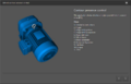
- The camera should be mounted parallel to the coordinate axes of the robot if possible. - That means either overhead, in front or from the side at an angle of 0°, 90° or 180°. This will simplify calibration significantly (see image on the right).
Camera configuration
The ifm O2D200 and O2D500 cameras use different tools for configuring the camera. The following sections only show a step by step summary, please read the camera's documentation for further info.
ifm O2D200

The image processing is done entirely in camera. To recognize a workpiece an "application" has to be set up containing the model of the workpiece. The camera is configured using the IFM Software efector dualis E2D200.
Communication with the robot control requires the following settings:
- TCP/IP settings:
- Without embedded control: Keep the factory defaul IP address or use one of your choice in the network of your computer.
- With Raspberry Pi-based embedded control: 192.168.3.49 or a different address in that same network but not 192.168.3.11. Since this ethernet port is used for connecting the computer you may need to use a network switch so you can connect both.
- With Phytec-based embedded control:
- Ethernet port 2 (recommended): 192.168.4.49 or a different address in that same network but not 192.168.4.11.
- Ethernet port 1: See Raspberry Pi-based control.
After changing the IP address you may need to update the IP address of your computer as described in section PC Network Configuration otherwise you may not be able to connect to the camera.
- An example camera configuration can be downloaded here - it is set up to recognize a 2 Euro coin in our lighting conditions and camera set up. (Your mileage may vary. This file is provided to make sure that parameters, such as IP and result output are correct.) To get it to actually recognize a coin, read the IFM documentation. The file has to be unzipped before loading it by right clicking on an unused folder in the "Applications" dialogue and selecting "Download to Sensor" followed by right clicking on the same folder and selecting "Activate". Not that the IP configuration of the camera is also updated (to the defaultsettings) when doing that (192.168.0.49).

- The Protocol Version must be V2 and the output format ASCII.

- Select you newly created project and click on the edit button on the LEFT.
- Then click on "Process Interface" and "Change Settings". The window "IO configuration" appears.
- In the "TCP/IP settings" set
- "Result Output" to On
- "Model Detail Output" to On
- "Start sring" to "start"
- "Stop string" to "stop"
- "Separator" tp "#"
- "Image output" may be On or Off. Set this to "On" if you want to be able to see the camera's image in CPRog/iRC, otherwise "Off" is recommended
- "Image format" to "Windows bitmap"
Make sure that the camera recognizes your object reliably enough before proceeding to the next step: Setting up the Robot Control.
ifm O2D500
The ifm O2D500 provides different operating modes, two of which are supported by our robot control:
- Contour presence control
- Advanced application
By default contour presence control does not send object IDs. This may be relevant if your robot needs to distinguish objects. An alternative communication preset can be loaded to include the object IDs.
Make sure you are using at least firmware version 1.27.9941 (see the title bar of the ifm configuration tool after connecting to the camera).
Protocol
Make sure the process interface protocol is set to V3: Open Device Setup -> Interfaces and check the setting of "Process interface version".
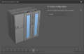
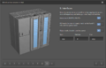
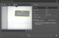
Creating a Coutour Presence Control Application
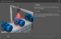
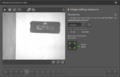
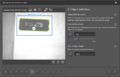
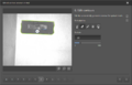
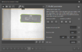
The fastest way to set up a simple image recognition application is via the contour presence control assistant. Simply follow the steps as shown in the screenshots and enter the following settings:
- in step 2: Set trigger to continuous or process interface (request images via the "Trigger Camera" robot program command).
- in step 7: Hint: consider setting "Orientation" to -180 - 180 so that the object is recognized in any orientation.
- in step 8: Set output interface to Ethernet
- in step 9: Enable "Model result" and "ROI results", "Object results" is optional. Set "Start" to either "star" or "start", "Delimiter" to "#" and "End" to "stop"
Setting up contour presence control
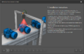
Step 1
Step 2
Step 3
Step 4
Step 5
Step 6
Step 7
Step 8
Step 9
Step 11


Coordinate Types
By default the camera sends image coordinates (pixel positions) which then need to be transformed by the robot control, see section Setting up the Robot Control on how to do the calibration. Alternatively the camera can be calibrated to do the coordinate transformation and send positions relatively to the robot in mm:
- Select your camera application and click "Edit application" below the "Application details" at the right side.
- If asked choose to change to advanced configuration (you can't use the assistant for this application afterwards).
- Open the "Images & trigger" configuration, then find "Calibration" button in the "Trigger & general" section.
- Follow the "Robot sensor calibration" wizard. Please refer to the camera's documentation if any issues occur.
The camera by default still sends the pixel position. To send the cartesian position you need to set the "Robot Coordinates" interface preset as explained in the next section.
Model ID and Interface Preset
By default the contour presence control mode does not send model IDs. If you need to distinguish objects change to an advanced application as described in the previous section. Then follow these steps:
- Open the Interfaces configuration of your camera application
- In the TCP/IP section check if the preset for igus robots is available. File:Ifm O2D500 Presets for iRC.zip.
- Select the preset for image coordinates unless you calibrated for robot coordinates and save the application.
Creating an Advanced Application
Creating an advanced application may be the faster approach if you know what you're doing or if you want to define multiple objects.
- Create a new application and select advanced application. There is no wizard to follow.
- Calibrate for robot coordinates as explained in the section "Coordinate Types" above.
- Load the interface preset as explained in the section "Model ID and Interface Preset" above.
- Define your models
- Save the application
Setting up the Robot Control

Now that the camera is ready to deliver object model and position information the robot control needs to be set up to connect to the camera and calculate the object/pick positions in 3D space.
- Start CPRog/iRC and connect it to the robot if you are using one with embedded control.
- Open the camera configuration: File -> Configure Interfaces -> Cameras
- Add a new camera of type "IFM O2D".
The configuration area should look similar to the screenshot on the right.
Please note: If you change camera settings, e.g. your camera application, the robot may continue receiving values by the old configuration until reconnected. To do this simply click "Apply" in the interface configuration of CPRog/iRC.
General Settings
These settings refer to the connection to the camera and enable it to be used in a robot program.
- Enabled: This enables the camera in CPRog/iRC. If disabled the values from the simulation section will be used. Keep this disabled if you are using an embedded control, otherwise CPRog/iRC might prevent the embedded control from receiving data from the camera.
- Image enabled: If an image is received it will be shown in the camera status section in CPRog/iRC.
- Name: This name identifies the camera in the robot program.
- Description: An optional description, this setting has no effect.
- IP address: IP address of the camera as set up earlier in this article.
- Port: Port number of the camera, by default 50010.
Coordinate Transformation Settings
This section defines whether and how coordinates from the camera are transformed.
Set the Source coordinate type to "Robot coordinates (mm)" if you calibrated the O2D500 to send robot coordinates. This way the coordinates are not changed by the robot control. Otherwise select "Image coordinates (px)" and follow the next steps to set up the robot control to transform the coordinates. Hint: for testing purposes it may be useful to temporarily select "Robot Coordinates" to see the raw pixel values.
These settings are used to calibrate the camera so that the correct positions in 3D space are calculated from the received data. Refer to the image on the right on how to measure these values.
We suggest calibrating each value step by step, click Apply to save the changes to the robot and check the change in the camera tab under the 3D view (see chapter "Camera Status"). It should become 'more correct' with each step.
- Origin: The position of the camera in the robot coordinate system (x/y/z value).
- Hint: Move your robot's gripper right under the camera and copy the X and Y position of the robot into the origin fields. Measure the Z distance, add it to the robot's position and enter it as the origin Z value.
- Alternatively move your robot to a nearby position (or the 0-position) and measure the X-, Y- and Z- distances from there.
- Pick Distance: Is the distance between the top of the workpiece and the camera.
- Hint: Place the object below the camera and measure the distance
- Look Vector: The viewing direction of the camera. In the image the camera looks down in negative Z direction.
- Hint: If your camera points down enter (0, 0, -1). If it points along a different axis change the vector accordingly.
- Up Vector: This vector defines the rotation of the camera around the target axis, i.e. top and bottom in a 2D image.
- Hint: If the camera is rotated by 90° or 180° along the Z axis you will need to enter one of the following values: (1 0 0), (-1 0 0), (0, 1, 0), (0, -1, 0), note that the Z value is always 0!
- Hint: Try to mount your camera at an angle that is a multiple of 90° to the robot coordinate system, otherwise you will need to calculate these values using sine and cosine.
- Scaling: The camera outputs the object position results in pixels and hands it over to the plugin. To calculate the robot target position the pixel values have to be multiplied with the scaling factor. The scaling factor is dependent on the distance between camera and the surface the camera looks at (see next section).
- Hint: Move your robot next to the object and note the X or Y position of both the robot (information tab) and the object (camera tab).
- Then move the robot by a certain distance (e.g. 5cm) along the X or Y axis (cartesian jog).
- Move the object so that it has the same relative distance to the robot and note the new X or Y position.
- From these values you can calculate the Scaling factor using the rule of three: Divide the actual distance (e.g. 5cm) by the distance of the first and second object position from the camera tab. Enter this value into the Scaling X and Y entries in the configuration area. If the previous value there is not 1 multiply it by your value.
Calibrating the coordinate axes: Place an object under the camera and move it along either the X or Y axis. Note the start and end positions as shown in the camera status tab and find the major motion direction (X or Y in positive or negative). Then jog the robot in cartesian base mode along the same axis. Does it's direction match that of the object? If not try changing Up Vector. You can also negate one or both scaling values to invert the axes given by the camera.
Solving object offsets Depending on the configuration of the camera your coordinates may be offset. To check whether this is the case place an object right under the camera (so that it's center point is in the middle of the picture). The recognized X and Y should be close to those set in Origin. If they are off by too much calculate the difference between the recognized X and Y and the origin. Then add or subtract that value from the origin.
Simulation Settings
The simulation settings are used when the camera is not enabled in CPRog/iRC. Simulation is not available in the embedded control. These values simulate the information received from the camera before transformation to 3D space, therefore the simulated object position will differ from these values.
- X, Y and Z: Simulated object position in camera image space (XY, usually 0-640 and 0-480) or robot space (XYZ in mm)
- Orientation: object orientation
- Model class: model class or -1 to simulate a failed recognition
Click "Save Project" to save the changes in CPRog/iRC and the embedded control (if connected). Test the settings carefully, preferably in simulation first, with a low override. Watch whether the robot collides with the ground surface or object.
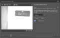
Camera Status

Once configured the status area in CPRog/iRC will show the status of the camera and the position and model class of the recognized object. If the camera image is enabled it will be shown there as well.
Using the camera in a robot program
The robot control provides 2 commands for accessing the camera: "Camera" and "Trigger Camera". The camera command copies the last received object data to a previously defined position variable and the model class to a number variable. If the camera is set up to continuously send data this is all you need. If the camera is set to be triggered by the process interface you can use the "Trigger Camera" command to request new data from the camera. This is useful to collect data at a certain moment.

The screenshot shows how the camera command is used in practice.
- Declare two variables using the store command: A position variable for the object position and a number variable for the model class.
- Use the Camera command to copy object information into the variables. This command does not wait, if no new information is available it will return the previous values again. If no object is recognized the model class will be -1, the position value must not be used in that case.
- Use an If statement to check whether the model class is greater than -1.
- In that case you may proceed to use the object position. In CPRog/iRC and TinyCtrl earlier than V12 only the cartesian object position is available, you can not use joint commands to move to the object. Joint commands in V12 and later may be faster than linear commands.

Attention 1: Your robot might move to the object slower than usual, especially if your robot has no orientation axis (e.g. gantries and deltas). To fix this you can overwrite the orientation values of the target position variable. The approach shown in the screenshot should work for all robot types.
Attention 2: In case of robot arms: Linear commands may not be able to move to your object position from each position. Try the following if an interpolation error occurs:
- Move to a defined position close to the camera zone before moving to the object.
- Overwrite the object orientation as described in Attention 1.
- Use the joint-by-variable command (supported in V12 and newer). This should work as long as the object position is reachable.
- Check manually whether the target positions are reachable: Read the object position from the cameras tab in CPRog/iRC, then use the jog buttons to move to that position.