Difference between revisions of "Robot Hardware Troubleshooting"
From Wiki
| (3 intermediate revisions by the same user not shown) | |||
| Line 2: | Line 2: | ||
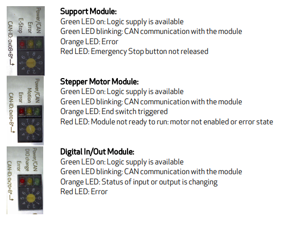
[[file:DIN-Rail-Module-LEDs.png|What do the LEDs of the DIN Rail Modules indicate?]] | [[file:DIN-Rail-Module-LEDs.png|What do the LEDs of the DIN Rail Modules indicate?]] | ||
{| class="wikitable" | {| class="wikitable" | ||
| − | ! Problem !! Cause !! | + | ! Problem !! Cause !! Solution |
|- | |- | ||
| Excessively jerky movement or acceleration and stall of the last joint of a robolink robot during initial set up of the robot|| Wrong encoder direction || [[Set_up,_testing_of_single_joints#Swap encoder direction|Swap encoder direction]] of this joint | | Excessively jerky movement or acceleration and stall of the last joint of a robolink robot during initial set up of the robot|| Wrong encoder direction || [[Set_up,_testing_of_single_joints#Swap encoder direction|Swap encoder direction]] of this joint | ||
| Line 8: | Line 8: | ||
|Green LEDs on the rail modules are off|| No power is supplied to the Modules||Check the power supply and the fuse. | |Green LEDs on the rail modules are off|| No power is supplied to the Modules||Check the power supply and the fuse. | ||
|- | |- | ||
| − | |Motors do not move || Check the emergency stop state. The red LED on the support module most not be on. The LED indicates emergency stop || Deactivate emergency stop. | + | |Motors do not move || Check the emergency stop state. The red LED on the support module most not be on. The LED indicates emergency stop || Deactivate (=release) emergency stop. |
|- | |- | ||
|The modules do not react to software commands. The green LEDs are not blinking, they are continuously on|| There must not be an empty slot between the support module of the electronics and the joint modules. The CAN connection is interrupted by such an empty slot.||Ensure there is no empty slot between the modules | |The modules do not react to software commands. The green LEDs are not blinking, they are continuously on|| There must not be an empty slot between the support module of the electronics and the joint modules. The CAN connection is interrupted by such an empty slot.||Ensure there is no empty slot between the modules | ||
| Line 14: | Line 14: | ||
|The motor stalls: it does not finish a motion and increases in pitch of sound.||This happens, when the load of the motor was too high.||Check if there was a collision. If this happens several times increase the motor current, see [http://www.cpr-robots.com/download/CPRog/UserGuide_igusRobolink.pdf chapter 7 of the manual]. | |The motor stalls: it does not finish a motion and increases in pitch of sound.||This happens, when the load of the motor was too high.||Check if there was a collision. If this happens several times increase the motor current, see [http://www.cpr-robots.com/download/CPRog/UserGuide_igusRobolink.pdf chapter 7 of the manual]. | ||
|- | |- | ||
| − | |CPRog cannot connect||Another application may be using the CAN connection||Close or reset the PCAN-View software, if it is running. | + | |CPRog cannot connect||Another application may be using the CAN connection||Close or reset the PCAN-View software, if it is running. If the fault persists, restart the PC and power-cycle the robot. |
|} | |} | ||
| Line 20: | Line 20: | ||
If none of the above solutions have the desired effect, or you have further questions, please [[Support Routes | get into contact with us]]. We are happy to help. | If none of the above solutions have the desired effect, or you have further questions, please [[Support Routes | get into contact with us]]. We are happy to help. | ||
| − | |||
| − | |||
| − | |||
| − | |||
| − | |||
| − | |||
| − | |||
| − | |||
| − | |||
| − | |||
| − | |||
| − | |||
| − | |||
| − | |||
| − | |||
[[Category:Robolink]][[Category:Mover]] | [[Category:Robolink]][[Category:Mover]] | ||
Latest revision as of 00:32, 6 June 2018
Modular control electronics / robolink robots
| Problem | Cause | Solution |
|---|---|---|
| Excessively jerky movement or acceleration and stall of the last joint of a robolink robot during initial set up of the robot | Wrong encoder direction | Swap encoder direction of this joint |
| Green LEDs on the rail modules are off | No power is supplied to the Modules | Check the power supply and the fuse. |
| Motors do not move | Check the emergency stop state. The red LED on the support module most not be on. The LED indicates emergency stop | Deactivate (=release) emergency stop. |
| The modules do not react to software commands. The green LEDs are not blinking, they are continuously on | There must not be an empty slot between the support module of the electronics and the joint modules. The CAN connection is interrupted by such an empty slot. | Ensure there is no empty slot between the modules |
| The motor stalls: it does not finish a motion and increases in pitch of sound. | This happens, when the load of the motor was too high. | Check if there was a collision. If this happens several times increase the motor current, see chapter 7 of the manual. |
| CPRog cannot connect | Another application may be using the CAN connection | Close or reset the PCAN-View software, if it is running. If the fault persists, restart the PC and power-cycle the robot. |
If none of the above solutions have the desired effect, or you have further questions, please get into contact with us. We are happy to help.
