Command Path
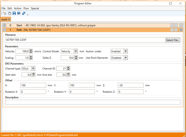
The Path command is used to move along the path of a .csv or .dxf file. This can be used for e.g. gluing applications. It is supported from CPRog/iRC V14-003-0. This article gives a short introduction and hints on how use this command.
Valid Files
- .dxf Files: Supported are the following elements:
- Line
- Point
- Polyline
- Circle
Note that Splines are not supported. Convert all Splines to Polylines. An Example how to export the .dxf file with SolidWorks is descriped on this page.
- .csv:
The following rule applies to the points in the .csv file:
X 2.91; Y 0.34; Z 16.79; A 124.15; B -70.0; C 0.0
X 2.39; Y 21.03; Z 172.47; A 113.77; B -70.0; C 0.0
";" is used as a separator between the values, decimal places are separated by a ".".
Command Settings
Filename

The corresponding file can be selected via "Select File...".
Parameters
The control mode can be used to select whether the points are to be approached with precise positioning or at a constant speed. It is not possible to approach the points accurately and at a constant speed at the same time, as this would require infinitely large accelerations. When automatic sorting is enabled, the elements are combined in the .dxf file if the start and end points are the same. In addition, the direction and order of the elements is changed to minimise the distance between elements. The dxf object can be enlarged or reduced using the Scale parameter. The object is scaled from the coordinate origin, which may result in a shift of the object depending on the position of the points. The Delta Z parameter can be used to set a Z height by which the TCP should move upwards between two closed objects. If your .dxf file contains point type elements, you can use the Use point elements parameter to select whether the robot should move to the points or not.
DIO parameter
The DIO parameter can be used to set which DIO or GSig is to be set when the course is run. A start distance can be specified, which indicates the distance before the first point at which the output should be set. The end distance can be used to set the distance before the last point at which the output should be deactivated.
Offset
If the position of the object to be moved needs to be moved, this can be done using the offsets in the x, y and z directions. If it is necessary to rotate the object, the rotation fields can be used. Rotation X rotates the .dxf file around the X axis, Rotation Y rotates the .dxf file around the Y axis and Rotation Z rotates the .dxf file around the Z axis. This means that if the file needs to be rotated in the X/Y plane, the file needs to be rotated around the Z axis.
Example Files
You can download [DXFExample.zip] to test the Command.