Robot Configuration File
The robot configuration files contain robot type dependent settings. Changing parameters in a robot configuration file may therefore affect multiple robot projects. This article shows how to change robot parameters.
![]() !!! Please be aware that changing these parameters might lead to collisions and other problems! Change the parameters with care and in small increments. Perform tests after the changes !!!
!!! Please be aware that changing these parameters might lead to collisions and other problems! Change the parameters with care and in small increments. Perform tests after the changes !!!
Configuration via CPRog/iRC
Some parameters can be easily changed via CPRog/iRC. Connect to the robot, then open the robot configuration area (File -> Robot Configuration). These settings are synchronized to the embedded control if it is connected when you click "Save".
Accessing the Configuration File
More specialized changes need to be done manually via the configuration file. Be careful with these settings since wrong values can lead to unexpected behavior, like the robot moving faster than expected.
Until version 13 the simulation and programming software on your PC and the embedded control both contain a copy of each robot configuration file. If you use a robot with embedded control you will need to change both, otherwise the simulation may act differently than the real robot. Version 14 always loads the configuration file from the robot but still contains a set on the PC for simulating standard robots.
Simulation (CPRog/iRC on the PC)
Find the installation directory of CPRog/iRC (usually directly on drive C:\ or in C:\Program Files). Then find the following file: Data\Robots\<category>\<type>\<type>.xml
You can edit the configuration file with a basic text editor. Reload the project in CPRog/iRC to apply changes.
Embedded Robot Control (real robot)

Via CPRog/iRC
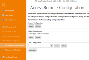
Version 12 (and newer) of CPRog/iRC simplifies access to the configuration files of the embedded control:
- Click File -> Access Configuration
- In the Robot Configuration section click "Load..." to load the current configuration from the embedded control.
- Change the file with a basic text editor
- Write it back by clicking "Write..."
- Restart the robot to apply changes
Manual Access
If older versions of CPRog/iRC are used the configuration file needs to be accessed manually.
- Use a SFTP client to connect to the embedded control
- Download the file /home/robot/TinyCtrl/Data/Robots/<category>/<type>/<type>.xml or /home/root/TinyCtrl/Data/Robots/<category>/<type>/<type>.xml
- Edit it with a basic text editor
- Upload it
- Restart the robot to apply changes
Parameters
The most important features that can be changed in the robot configuration file are the following. Note that only robot axes are configured here, not external or gripper axes.
| Line | Parameter | Description |
|---|---|---|
| BusConfiguration | CycleTimeMS | Interval at which motion is calculated and I/O is handled |
| BusConfiguration | GapMS | Wait this amount of ms between sending position commands to each axis. Can solve or introduce communication issues. Try values of 0-2 but must be less than CycleTimeMS/number of axes |
| BusConfiguration | PreciseTiming | Use precise timer for the motion loop (only on embedded control). This can solve communication issues but increases processor load. Only use on Raspberry-Pi-based systems! |
| Joint | ID | CAN ID of each robot axis |
| Joint | GearScale | Gear Scale and Axis Direction |
| RemoteConfiguration | IP | IP address of the embedded control (only relevant for CPRog/iRC) |
| TinyCtrl | DebugMode | Disables error checks - DO NOT CHANGE! |
| Kinematic | Kinematic dependent parameters including the lengths of robot arm segments | |
| SoftwareMinMax | Axis motion limits (mm or degrees) | |
| UnrefMinMaxIgnore | Ignore 'SoftwareMinMax' when the robot is unreferenced | |
| JointVelocities | Maximum velocities of each axis | |
| JointAccelerations | Maximum accelerations of each axis | |
| JointAccelerationIncs | Increase of acceleration of each axis | |
| CartVelocities | VelTrans | Maximum cartesian velocity (mm/s) |
| CartVelocities | VelOri | Maximum cartesian orientation velocity (degrees/s) |
| PathGeneration | GeneratorType | Path generator type (01Joint or 02Linear) |
| PathGeneration | SlicingMS | Time precision (should not be much lower than CycleTimeMS |
| PathGeneration | LookAhead, SmoothDist | See Motion Smoothing |
| Referencing | Mandatory | If set to true the robot program can only be started if the robot is referenced. Disabling this can lead to collisions. |
| Brake | Active | Enables the motor brake function |
| Brake | DOutChannel | DOut channel used for the brake (internal numbering, DOut21 in CPRog/iRC is number 20 here) |
| Velocities | JogJoint | Defines the jog velocity while jogging the robot in joint mode (value 0-1, percent of max velocity of each axis) |
| Velocities | JogCart, JogOri | Defines the cartesian velocity while jogging the robot (in mm/s and degrees/s) |
Note: The JointVelocities, CartVelocities etc. lines may appear with a number at the end of the tag name (e.g. JointVelocities2). These are alternative configuration sets intended for robots that are available in different configurations (e.g. 24V and 48V). The embedded control choses the active velocities set depending on the value of "VelocitySetting" in the Project Configuration File. CPRog/iRC saves this value in CPRFrontend.xml.
Joint and cartesian velocity

The configuration contains multiple sets of velocity and acceleration parameters. If your robot control uses a voltage of 24V use the tags JointVelocities, CartVelocities etc. If it uses 48V use JointVelocities2, CartVelocities2 etc.
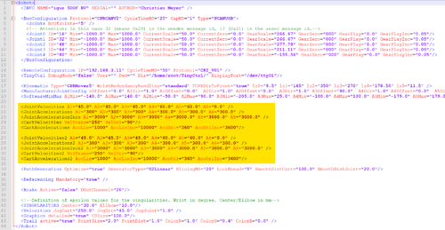
The tag "JointVelocities" defines the maximum rotational velocity of each joint in °/s (or linear mm/s in case of linear axes). Note that the tag in the second line ends with "2", this is for the 48V configuration.
<JointVelocities A1="500" A2="500" A3="300" A4="120" />
<JointVelocities2 A1="500" A2="500" A3="300" A4="120" />
The tag "CartVelocities" defines the cartesian motion and rotation velocity limits.
<CartVelocities VelTrans="250" VelOri="90" />
<CartVelocities2 VelTrans="250" VelOri="90" />
- During manual jogging only 50% of this velocity is allowed. The full velocity is reached during robot program replay with override at 100% and motion command velocity at 100%.
- When increasing the velocity, problems may occur:
- Overcurrent Error when the current consumption is too high.
- Position Lag Error when the joints PID controller cannot reach the set point commands fast enough
Using the Config Software ModuleCtrl, it is possible to change the joint module parameters, such as motor current.
Joint acceleration
Similarly to the velocity limits the joint accelerations can be changed by setting the following parameters:
<JointAccelerations A1="3000" A2="3000" A3="3000" A4="400.0" A5="100.0" A6="100.0" />
<JointAccelerationIncs A1="9000" A2="9000" A3="9000" A4="1200.0" A5="100.0" A6="100.0" />
<CartAccelerations AccLin="3000" AccLinInc="9000" AccOri="360" AccOriInc="3600" />
As mentioned above there may be a second set of these lines where each tag ends with "2". These are for the 48V configuration.
Joint min/max travel limits
The tag "SoftwareMinMax" defines the allowed motion ranges for the joints. It is not possible to move the joint out of these (virtual) boundaries.
<SoftwareMinMax A1Min="0" A1Max="500" A2Min="0" A2Max="500" A3Min="0" A3Max="100.0" A4Min="-179.0" A4Max="179.0" />
Note: When increasing these limits, collisions might occur that would have been prevented otherwise!