Tool Configuration
Each robot application needs a specific tool, e.g. a gripper, magnet, glue applicator etc. that offsets the tool center point (TCP) by a certain distance from the tool flange. The tool configuration files let you define this offset, 3D files for visualization in iRC/CPRog and how the tool is controlled (only for some tool types).
This article explains how to change to a different tool, how to install a new tool and how to create your own tool configuration.
See also category Tool for further articles including hardware integration.
Changing Tools

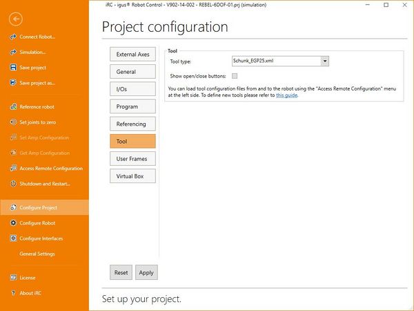
After connecting iRC/CPRog to the robot you can select a tool in the project configuration menu ("File" → "Configure Project" → "Tool"). Select a tool in the drop down box and click apply. In V13 a restart of the robot control is necessary, in V14 it is optional.
Note that you can only select tools that are installed to the robot. Not all tools available on your PC may be installed there. Read the following section on how to install new tools.
Installing a New Tool

This section explains how to add a tool configuration, assuming the configuration already exists. Read section "Configuring a Tool" on how to create a new tool configuration.
iRC/CPRog on PC (for simulation)
Open the installation folder of iRC/CPRog, e.g. C:\iRC-igusRobotControl. In there open the folder "Data" → "Tools". Copy your tool configuration and 3D files there.
Embedded Control
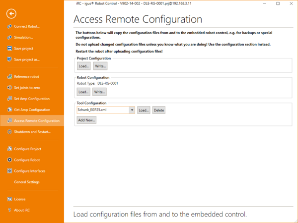
You can install new tools to the robot control via the "File" → "Access Remote Configuration" menu in iRC/CPRog. In section "Tool Configuration" click "Add New...", then select the tool configuration file to install.
To download a tool configuration from the robot to the PC or to delete a tool select it in the drop down box and click "Load..." or "Delete".
Creating a Tool
The XML-based tool configuration file can be edited using a basic text editor. To create a new tool copy an existing tool configuration as a base, then edit its entries. The following sections explain all parameters you may want to change.
Basic configuration
The general structure of the tool configuration looks like this:
<?xml version="1.0" encoding="utf-8"?>
<Tool>
  <INFO NAME="ParallelGripper" AUTHOR="" />
  <OFFSET OffsetX="0" OffsetY="0" OffsetZ="105" OffsetA="0.0" OffsetB="0.0" OffsetC="0.0" />
  <CAD FileStandard="FestoPG_open.obj" FileActive="FestoPG_closed.obj" FlipMesh="True" />
  <KINEMATIC Motion="Digital" MotionVel="10" />
  <INTERFACE Protocol="digital" ChannelOpenClose="11" ChannelEnable="12" />
</Tool>
- INFO defines information that don't affect functionality
- OFFSET defines the offset (position and rotation) of the tool center point, relative to the tool base (or tool flange of the robot)
- CAD defines optional 3D mesh files for visualization
- KINEMATIC defines how the tool motion is calculated
- INTERFACE specifies how the tool is controlled
INFO
<INFO NAME="ParallelGripper" AUTHOR="" />
You may give the tool a name and enter the author of the configuration file. These values currently are not used.
OFFSET
<OFFSET OffsetX="0" OffsetY="0" OffsetZ="105" OffsetA="0.0" OffsetB="0.0" OffsetC="0.0" />
OffsetX/Y/Z defines the distance from the tool center point (gripping/dispensing position etc) in mm. OffsetZ is the tool's length if it is not excentric.
OffsetA/B/C rotates the TCP in degrees. Few tools need this.
CAD
<CAD FileStandard="FestoPG_open.obj" FileActive="FestoPG_closed.obj" FlipMesh="True" />
Here you can set 3D mesh files that are shown in the 3D view for open and closed state. The files must be in OBJ format without separate material files.
- If Kinematic is set to "digital" FileStandard is used for the open state and FileActive for the closed state.
- If Kinematic is set to "linear", "rotational" or "rotationaltwofinger" FileActive will be animate a motion as specified in "KINEMATIC".
FlipMesh flips the drawing order of the mesh, try changing this in case of displaying issues. The value must bei "True" or "False"
KINEMATIC
<KINEMATIC Motion="digital" MotionVel="10"/>
If "Motion" is set to "digital" the visualization only shows the tool open or closed (or active / inactive). Use this for tools that are controlled via digital I/O or if the motion is not described by the other types.
<KINEMATIC Motion="linear" MotionMin="10" MotionMax="100.0" MotionVel="15.0" />
Set "Motion" to "linear" for tools that move linearly and are controlled by a stepper motor module. "MotionMin" and "MotionMax" define the open / close position of the stepper in mm, "MotionVel" is the motion velocity in mm/s.
<KINEMATIC Motion="rotational" MotionMin="10" MotionMax="100.0" MotionVel="15.0" MotionOffsetX="0.0" MotionOffsetY="0.0" MotionOffsetZ="0.0"/>
Set "Motion" to "rotational" or "rotationaltwofinger" for a gripper that rotates its fingers. Units are in degrees. MotionOffsetX/Y/Z define the point around which the finger rotates. In case of rotationaltwofinger this is symmetrically mirrored.
INTERFACE
<INTERFACE Protocol="digital" ChannelOpenClose="11" ChannelEnable="12" />
Set "Protocol" to "digital" if your tool is controlled by digital IO or if you only want control it manually (i.e. not via the Tool command). The digital output "ChannelOpenClose" is disabled for open and enabled for closed. "ChannelEnable" is always enabled when the robot are enabled. Numbering starts at 1, so enter "21" for DIn21.
Note that some tools require different IO, e.g. a rising edge on one channel to open and a rising edge on another to close. This currently is not supported by the tool configuration. Set the channels in INTERFACE to invalid values, e.g. 11 and 12, then create the signals in the motion or logic program using the digital output and wait commands. It may be useful to create short (3-4 lines) programs for open and close and simply call them via the subprogram command.
<INTERFACE Protocol="bus" BusID="112" GearScale="-10.0" GearZero="210.0" CurrentScale="0.3" CurrentZero="150.0" MaxCurrent="900"/>
NOTE: Tool axes (protocol "bus") currently are not supported!
Set "Protocol" to "bus" if the tool actuates by a stepper motor that is connected to a CPR/iRC stepper motor module. "BusID" is the CAN ID (find a translation table in the iRC user guide). "GearScale" is the translation factor from motor steps to mm or degrees. "GearZero" is the offset from 0 in motor steps. The Current parameters are not used.
The electrical setup of the stepper is equal to robot and external axes.
Note that there currently is no collision detection. The motor will push the gripper against the object or the end stop until iRCs calculations have reached the target position. This means the currents of the motor (see Firmware Parameter Configuration) must be set low enough that the stepper can loose steps without breaking anything.