Difference between revisions of "Digital Inputs / Outputs"
m |
|||
| (61 intermediate revisions by 3 users not shown) | |||
| Line 1: | Line 1: | ||
| − | + | The control electronics come with a digital input / output module (DIO Module). This page shows how to connect actuators, valves or sensors to the module. | |
| − | The | + | The DIO module provides 7 digital inputs and 7 digital outputs. The inputs are electrically decoupled from the control electronics by an optocoupler and accept 24V input signals. |
| + | * The outputs are solid state relays which can switch up to 500 mA per channel. The DIO module does not provide its own supply voltage for the DIOs. | ||
| + | * The inputs are optocouplers which can detect a 24 V Signal. Signal and signal ground needs to be connected to the DIO Module. | ||
| − | + | Please note: the integrated DIO modules of the igus ReBeL are not electrically decoupled from the control electronics, they share 24V and GND from the power supply. | |
| − | Indicators: When the state of a sensor input or | + | Indicators: When the state of a sensor input or an output changes the yellow LED on the top blinks once. |
| − | == | + | ==Electrical connections== |
| + | [[File:DIO-Connections.PNG|400px|thumb|Digital IO connection]] | ||
| + | [[file:DIO_pinout.png|thumb|400px|left]] | ||
| + | ===Connect Digital Inputs:=== | ||
| + | * Disconnect the robot/electronics from power. | ||
| + | * Connect the ground pin (Output connector 1, to GND) | ||
| + | * Supply 24V to one of the input pins | ||
| + | * Example on the left: 24V via switch to input pin 4 | ||
| + | * Result in CPRog: digital input Din24 is triggered | ||
| − | + | ===Connect Digital Outputs=== | |
| + | *Disconnect the robot/electronics from power. | ||
| + | *Connect the supply pin to 24V power supply | ||
| + | *The supply is forwarded to one of the outputs pins via reed relays | ||
| + | *Connect a valve or another component to the output pin | ||
| + | *Connect the component to GND to close the electrical circuit | ||
| + | *See the example with the lamp on output 5 on the left. | ||
| + | |||
| + | ===Start the Robot and iRC / CPRog=== | ||
| + | *Connect electronics/robot to power, ensure the emergency stop button is disengaged. | ||
| + | *Start CPRog: | ||
| + | **Reset and Enable the robot | ||
| + | **Set DOut 25 to true to switch on the lamp | ||
| + | <br clear=all> | ||
| + | |||
| + | ==Nomenclature== | ||
| + | ===Mover=== | ||
| + | To control the IOs in Software, all ''CPR robots'', such as the Mover, provide digital inputs and outputs that are named channel 1 through 4. | ||
| − | + | ===Modular Control Electronics / igus robolink arms/ igus gantry robots=== | |
| − | + | In contrast, the ''igus robolink arms and gantry robots'' use the following nomenclature: | |
| − | |||
| − | |||
| − | |||
| − | |||
| − | |||
| − | The | + | The Modular control electronics for these robots can be equipped with more than one DIO module. To address pins 1-7 of the inputs/outputs of every module, the modules are in three different address spaces: |
| − | + | * For the first DIO-Module: Channels 21 through 27, i.e. DOut21, DOut22,... or DIn21, DIn22,... | |
| − | + | ** DOut21 switches pin 1 of DIO module 1. | |
| + | ** DOut22 switches pin 2 of DIO module 1. | ||
| + | **.. | ||
| + | **DOut27 switches pin 7 of DIO module 1. | ||
| − | + | * For the second DIO-Module: Channels 31 through 37 | |
| + | ** DOut31 switches pin 1 of DIO module 2. | ||
| + | ** DOut32 switches pin 2 of DIO module 2. | ||
| + | **.. | ||
| + | **DOut37 switches pin 7 of DIO module 2. | ||
| − | + | * For the third DIO-Module: Channels 41 through 47 | |
| − | * For the | + | ** DOut41 switches pin 1 of DIO module 3. |
| − | * | + | ** DOut42 switches pin 2 of DIO module 3. |
| − | * | + | **... |
| + | **DOut47 switches pin 7 of DIO module 3. | ||
| + | The nomenclature for the inputs is DInXX analogous to the DOutXX nomenclature explained above. | ||
The maximum amount of DIO modules installed in the control electronics is currently 3. | The maximum amount of DIO modules installed in the control electronics is currently 3. | ||
| Line 36: | Line 67: | ||
==How to use the outputs== | ==How to use the outputs== | ||
| − | [[ | + | [[file:DIO_add_digitalout.png|thumb|600px|Add Digital Out command]] |
| − | + | The output signals can be switched on or off with the 'Digital Out' command in CPRog (see screenshot on the right). To add this command in the program editor click "Action" -> "Digital Output". | |
| − | The output signals can be switched on or off with the 'Digital Out' command in CPRog (see screenshot on the right). | ||
| − | |||
| − | |||
| − | |||
Please be aware that the outputs can only be switched on when the robot is enabled! | Please be aware that the outputs can only be switched on when the robot is enabled! | ||
[[file:Caution.png|frameless|50px]]The outputs must not drive more then 500 mA, also not at startup! Avoid higher currents, e.g. caused by the inrush current of capacitors! Use a secondary relay in this case to prevent damage to the DIO module. | [[file:Caution.png|frameless|50px]]The outputs must not drive more then 500 mA, also not at startup! Avoid higher currents, e.g. caused by the inrush current of capacitors! Use a secondary relay in this case to prevent damage to the DIO module. | ||
| + | |||
| + | Here an '''example''' on [[How to operate a gripper using CPRog and the Modular Control Electronics]] | ||
| + | <br clear=all> | ||
==How to use the inputs== | ==How to use the inputs== | ||
| − | The digital inputs can be used e.g. in if-then-else statements | + | [[file:DIO_cprog_input_program.png|thumb|600px|right|Check status of Digital Input in an if-statement ]] |
| + | The digital inputs can be used e.g. in if-then-else statements. | ||
| − | The | + | The picture on the right side shows a simple example: The first input of the first DIO module (DIn21) is checked. If it is true than the first output of the first DIO module (DOut21) is switched on; otherwise it is switched off. |
| + | ==Additional IO Modules== | ||
| − | + | If not ordered otherwise each robot control cabinet comes with one digital IO module. The following guides explain how you can add up to 2 additional modules: | |
| − | + | * How to add [[Additional DIO-Modules]] | |
| + | * How to add [[Additional DIO-Boards of the DCi Control Electronics]] | ||
| − | |||
| − | |||
| − | + | [[Category:CPRog]][[Category:robolink]][[Category:Robot Programming]][[Category:DIO_Modules]] | |
| − | [[Category: | ||
Latest revision as of 14:17, 21 June 2024
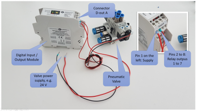
The control electronics come with a digital input / output module (DIO Module). This page shows how to connect actuators, valves or sensors to the module.
The DIO module provides 7 digital inputs and 7 digital outputs. The inputs are electrically decoupled from the control electronics by an optocoupler and accept 24V input signals.
- The outputs are solid state relays which can switch up to 500 mA per channel. The DIO module does not provide its own supply voltage for the DIOs.
- The inputs are optocouplers which can detect a 24 V Signal. Signal and signal ground needs to be connected to the DIO Module.
Please note: the integrated DIO modules of the igus ReBeL are not electrically decoupled from the control electronics, they share 24V and GND from the power supply.
Indicators: When the state of a sensor input or an output changes the yellow LED on the top blinks once.
Electrical connections
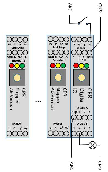
Connect Digital Inputs:
- Disconnect the robot/electronics from power.
- Connect the ground pin (Output connector 1, to GND)
- Supply 24V to one of the input pins
- Example on the left: 24V via switch to input pin 4
- Result in CPRog: digital input Din24 is triggered
Connect Digital Outputs
- Disconnect the robot/electronics from power.
- Connect the supply pin to 24V power supply
- The supply is forwarded to one of the outputs pins via reed relays
- Connect a valve or another component to the output pin
- Connect the component to GND to close the electrical circuit
- See the example with the lamp on output 5 on the left.
Start the Robot and iRC / CPRog
- Connect electronics/robot to power, ensure the emergency stop button is disengaged.
- Start CPRog:
- Reset and Enable the robot
- Set DOut 25 to true to switch on the lamp
Nomenclature
Mover
To control the IOs in Software, all CPR robots, such as the Mover, provide digital inputs and outputs that are named channel 1 through 4.
Modular Control Electronics / igus robolink arms/ igus gantry robots
In contrast, the igus robolink arms and gantry robots use the following nomenclature:
The Modular control electronics for these robots can be equipped with more than one DIO module. To address pins 1-7 of the inputs/outputs of every module, the modules are in three different address spaces:
- For the first DIO-Module: Channels 21 through 27, i.e. DOut21, DOut22,... or DIn21, DIn22,...
- DOut21 switches pin 1 of DIO module 1.
- DOut22 switches pin 2 of DIO module 1.
- ..
- DOut27 switches pin 7 of DIO module 1.
- For the second DIO-Module: Channels 31 through 37
- DOut31 switches pin 1 of DIO module 2.
- DOut32 switches pin 2 of DIO module 2.
- ..
- DOut37 switches pin 7 of DIO module 2.
- For the third DIO-Module: Channels 41 through 47
- DOut41 switches pin 1 of DIO module 3.
- DOut42 switches pin 2 of DIO module 3.
- ...
- DOut47 switches pin 7 of DIO module 3.
The nomenclature for the inputs is DInXX analogous to the DOutXX nomenclature explained above. The maximum amount of DIO modules installed in the control electronics is currently 3.
Attention: The DIO are also used by the PLC Interface (if active), refer to this.
How to use the outputs
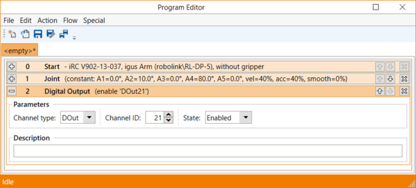
The output signals can be switched on or off with the 'Digital Out' command in CPRog (see screenshot on the right). To add this command in the program editor click "Action" -> "Digital Output".
Please be aware that the outputs can only be switched on when the robot is enabled!
![]() The outputs must not drive more then 500 mA, also not at startup! Avoid higher currents, e.g. caused by the inrush current of capacitors! Use a secondary relay in this case to prevent damage to the DIO module.
The outputs must not drive more then 500 mA, also not at startup! Avoid higher currents, e.g. caused by the inrush current of capacitors! Use a secondary relay in this case to prevent damage to the DIO module.
Here an example on How to operate a gripper using CPRog and the Modular Control Electronics
How to use the inputs
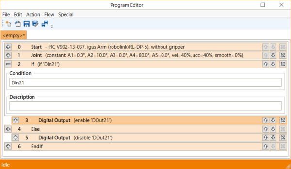
The digital inputs can be used e.g. in if-then-else statements.
The picture on the right side shows a simple example: The first input of the first DIO module (DIn21) is checked. If it is true than the first output of the first DIO module (DOut21) is switched on; otherwise it is switched off.
Additional IO Modules
If not ordered otherwise each robot control cabinet comes with one digital IO module. The following guides explain how you can add up to 2 additional modules:
- How to add Additional DIO-Modules
- How to add Additional DIO-Boards of the DCi Control Electronics


