Difference between revisions of "DCi quickstart guide"
m (link changed) |
|||
| (74 intermediate revisions by 3 users not shown) | |||
| Line 1: | Line 1: | ||
=Introduction= | =Introduction= | ||
| − | |||
| − | |||
This guide is meant to serve as the initial instruction set to get you going with the DCi robot. | This guide is meant to serve as the initial instruction set to get you going with the DCi robot. | ||
| Line 7: | Line 5: | ||
[[file:caution.png|20px|left|frameless]] Never hotplug anything. Switch off the robot prior to making any connection. | [[file:caution.png|20px|left|frameless]] Never hotplug anything. Switch off the robot prior to making any connection. | ||
| − | =Switch on and | + | =Documentation= |
| − | #Once you have unpacked your DCi Robot, place it on a level surface, remove all zip-ties and packaging material from the robot arm. Make sure that there is sufficient free space around the robot to operate the arm. | + | |
| + | Please also have a look inside the user guide for the embedded control of the robolink-DCi: | ||
| + | ==Before 2019== | ||
| + | * EN: [[https://www.cpr-robots.com/download/TinyCtrl/UserGuide_CPR-robolink-DCi_EN.pdf UserGuide_CPR-robolink-DCi_EN.pdf (v1.1)]] | ||
| + | * DE: [[https://www.cpr-robots.com/download/TinyCtrl/Bedienungsanleitung_CPR-robolink-DCi_DE.pdf Bedienungsanleitung_CPR-robolink-DCi_DE.pdf (v1.1)]] | ||
| + | |||
| + | You can find the documentations for the CPRog programming environment in the according section [[Software Updates]]. | ||
| + | * EN: [[media:UserGuide_CPR-robolink-DCi_EN_v1.2.pdf|UserGuide_CPR-robolink-DCi_EN.pdf (v1.2)]] | ||
| + | * DE: [[media:Bedienungsanleitung_CPR-robolink-DCi_DE_v1.2.pdf|Bedienungsanleitung_CPR-robolink-DCi_DE.pdf (v1.2)]] | ||
| + | |||
| + | ==Since 2019== | ||
| + | |||
| + | ==Connections== | ||
| + | For robolink DCi sold since 2019: | ||
| + | |||
| + | [[file:robolink_dci_dio_pinout_2019.jpg|600px]] | ||
| + | |||
| + | 3 additional inputs and outputs are accessible from inside the robot base (DIn25-27 and DOut25-27). | ||
| + | |||
| + | =Switch on and move= | ||
| + | #Once you have unpacked your DCi Robot, place it on a level surface, remove all zip-ties that hold the robot in the shipping position and all packaging material from the robot arm. Make sure that there is sufficient free space around the robot to operate the arm. | ||
#Connect the Teach Pendant (that is what we call the remote control with the display) to the rear of the robot and tighten the fixing screws of the connector. | #Connect the Teach Pendant (that is what we call the remote control with the display) to the rear of the robot and tighten the fixing screws of the connector. | ||
| − | #The robot requires a 24V 4A. A power supply is | + | #The robot requires a power supply rated for 24V and minimum 4A. A power supply is usually shipped with the DCi robot. Connect it to the back of the robot. |
| − | #Connect the power supply to the mains and switch on the robot at the | + | #Connect the power supply to the mains and switch on the robot at the rear. |
| − | #*The LEDs at the back of the robot will light up and the Teach Pendant will | + | #*The LEDs at the back of the robot will light up and the Teach Pendant will initialize. |
#* After 20s most of the green LEDs at the back of the robot should be blinking. This indicates that communication has been established to the stepper motor modules and the digital input/output module(s). | #* After 20s most of the green LEDs at the back of the robot should be blinking. This indicates that communication has been established to the stepper motor modules and the digital input/output module(s). | ||
| − | # If the red emergency stop button | + | # If the red emergency stop button is depressed, disengage it by rotating and pulling upwards at the button. |
| − | # Next to a status message, you should see two soft-buttons in the touch display: Reset and | + | # Next to a status message, you should see two soft-buttons in the touch display: ''Reset'' and ''Enable''. Click ''Reset'', followed by ''Enable'' to reset the robot and enable the motors. |
# Now there should be a red message in the display saying that the robot is not referenced yet. We will ignore that for now and do the referencing later. | # Now there should be a red message in the display saying that the robot is not referenced yet. We will ignore that for now and do the referencing later. | ||
| − | # Push the "Jog" Menu button at the top of the touch display. | + | # Push the "Jog" Menu button at the top of the touch display. [[file:JogDialogTeachPendant.png|300px|right]] |
# Using the joystick, you should now be able to jog the first, second and third axis to verify their function (slowly rotate the joystick left and right, up-down, left-right). | # Using the joystick, you should now be able to jog the first, second and third axis to verify their function (slowly rotate the joystick left and right, up-down, left-right). | ||
# Push A5 at the bottom of the screen to gain control of joint 4 and 5. Move it by rotating the joystick left and right, up-down. | # Push A5 at the bottom of the screen to gain control of joint 4 and 5. Move it by rotating the joystick left and right, up-down. | ||
| + | <br clear=all> | ||
=Reference= | =Reference= | ||
| − | There is a whole | + | [[file:robolink_dci_referencing_position.png|frameless|right]] [[file:ReferenceDialogTeachPendant.png|300px|right]] |
| − | #Move the robot close to its reference switch position: each axis has a metal pin in the joint that is used to sense the reference position. Since you are doing this step for the first time and the robot might still be "folded up" for shipping, jog the joints until the robot is in this position. | + | The software that is running on the embedded robot control needs to know what position the robot is in. At the moment it does not. Therefore we need to reference the robot. |
| − | #On the | + | There is a whole article on [[Referencing robolink|referencing the robolink robots]] in this wiki. In short: |
| − | #Start by pushing " | + | #Move the robot close to its reference switch position: each axis has a metal pin in the joint that is used to sense the reference position. Since you are doing this step for the first time and the robot might still be "folded up" for shipping, jog the joints until the robot is in this position (see image on the right). |
| − | #After | + | #On the display, select the "Enable" button at the top to open the referencing dialog. |
| + | #Start by pushing "Ref A1". Once the joint has stopped moving, continue with joint A2, A3 and so forth. | ||
| + | #After, once the robot has stopped moving, i.e. the referencing has finished, push ''Reset'' and ''Enable'' the robot again to apply the reference values that have been found during the referencing operation. | ||
| + | <br clear=all> | ||
=Run a program= | =Run a program= | ||
| + | [[file:PlayDialogTeachPendant.png|300px|right]] | ||
The DCi robots come with a test program. Once the robot is referenced, | The DCi robots come with a test program. Once the robot is referenced, | ||
# push the "Play" button at the top of the display to get to the program dialog. | # push the "Play" button at the top of the display to get to the program dialog. | ||
| − | # To run the program press " | + | # To run the program press "Single Play". - Ensure that there is sufficient free space around the robot to avoid collisions. |
| − | # The robot should play the pre-recorded | + | # The robot should play the pre-recorded program. |
| + | |||
| + | *In order to run a program continuously, you can push the "Cont. Play" button instead. | ||
| + | *The Override slider sets the speed as a percentage of the maximum speed configured in the firmware. | ||
| + | <br clear=all> | ||
| + | =DIO Module PinOut= | ||
| + | ==Before 2019== | ||
| + | The digital I/O module can be used to operate, e.g. a gripper attached to the robot or to communicate with the external world. | ||
| + | [[file:robolink_dci_dio_pinout.png|400px|right|PinOut DCi DIO Module]] | ||
| + | *PWR: linked though to internal 24V supply voltage. | ||
| + | *GND: linked through to internal ground. | ||
| + | *DIn1-4: digital inputs 1-4. Going via 12k into opto-coupler: https://www.vishay.com/docs/84181/tcmt4100.pdf | ||
| + | *DOut1-4: digital outputs 1-4. Going directly into relay: http://omronfs.omron.com/en_US/ecb/products/pdf/en-g3vm_62c1_f1.pdf, which switches internal 24V Supply Voltage through to Dout1-4. | ||
| + | |||
| + | In the CPRog Software, the pins labelled | ||
| + | * DOut 1-4 are addressed with DOut21 - DOut24. | ||
| + | * DIn 1-4 are addressed with DIn21 - DIn24 | ||
| − | =Connect the robot to a Windows PC | + | Once you write a program (see section below), you can address the inputs and outpouts as described [[Digital_Inputs_/_Outputs#How_to_use_the_outputs|here]] |
| − | In order to generate your own programs, it is best to connect it to a Laptop or PC running | + | |
| + | <br clear=all> | ||
| + | |||
| + | ==Since 2019== | ||
| + | The digital I/O module can be used to operate, e.g. a gripper attached to the robot or to communicate with the external world. | ||
| + | [[file:robolink_dci_dio_pinout_2019.jpg|400px|right|PinOut DCi DIO Module 2019]] | ||
| + | *PWR: linked though to internal 24V supply voltage. | ||
| + | *GND: linked through to internal ground. | ||
| + | *DIn21-24: digital inputs to read high/low signals from external/additional devices. Going via 12k into opto-coupler: https://www.vishay.com/docs/84181/tcmt4100.pdf | ||
| + | *DOut21-24: digital outputs to switch external/additional devices. Going directly into relay: http://omronfs.omron.com/en_US/ecb/products/pdf/en-g3vm_62c1_f1.pdf, which switches internal 24V Supply Voltage through to Dout1-4. | ||
| + | |||
| + | |||
| + | Once you write a program (see section below), you can address the inputs and outpouts as described [[Digital_Inputs_/_Outputs#How_to_use_the_outputs|here]] | ||
| + | |||
| + | <br clear=all> | ||
| + | |||
| + | =Connect the robot to a Windows PC to start recording/writing your own programs= | ||
| + | In order to generate your own programs, it is best to connect it to a Laptop or PC running Windows. This will allow you to record/generate a program or path that can later be uploaded to the embedded robot control, so that the laptop is no longer required for operation. | ||
| + | |||
| + | '''Initially, please install [[CPRog Downloads|iRC]] on your Windows PC''' | ||
{{Connect DCi Robot/TinyCtrl to a Laptop via LAN}} | {{Connect DCi Robot/TinyCtrl to a Laptop via LAN}} | ||
| − | Once referenced, you can start recording a program as | + | Once referenced, you can start recording a program as shown in the video below and this article: [[CPRog Examples]]. |
| + | {{#evt: | ||
| + | service=youtube | ||
| + | |id=https://youtu.be/9LWbj4UqOnw | ||
| + | |alignment=center | ||
| + | }} | ||
| + | <br clear=all> | ||
| + | |||
| + | For details on the available commands, have a look at | ||
*Command Reference EN: [http://www.cpr-robots.com/download/CPRog/CPR_CommandReference.pdf CPRog Command Reference] | *Command Reference EN: [http://www.cpr-robots.com/download/CPRog/CPR_CommandReference.pdf CPRog Command Reference] | ||
| Line 45: | Line 111: | ||
*Documentation / Manual EN: [http://www.cpr-robots.com/download/CPRog/UserGuide_igusRobolink.pdf robolink User Guide] | *Documentation / Manual EN: [http://www.cpr-robots.com/download/CPRog/UserGuide_igusRobolink.pdf robolink User Guide] | ||
*Documentation / Manual DE: [http://www.cpr-robots.com/download/CPRog/Bedienungsanleitung_igusRobolink_DE.pdf robolink Bedienungsanleitung] | *Documentation / Manual DE: [http://www.cpr-robots.com/download/CPRog/Bedienungsanleitung_igusRobolink_DE.pdf robolink Bedienungsanleitung] | ||
| + | [[Category:TinyCtrl]][[Category:robolink]] | ||
Latest revision as of 10:09, 16 August 2023
Introduction
This guide is meant to serve as the initial instruction set to get you going with the DCi robot.
Never hotplug anything. Switch off the robot prior to making any connection.
Documentation
Please also have a look inside the user guide for the embedded control of the robolink-DCi:
Before 2019
- EN: [UserGuide_CPR-robolink-DCi_EN.pdf (v1.1)]
- DE: [Bedienungsanleitung_CPR-robolink-DCi_DE.pdf (v1.1)]
You can find the documentations for the CPRog programming environment in the according section Software Updates.
Since 2019
Connections
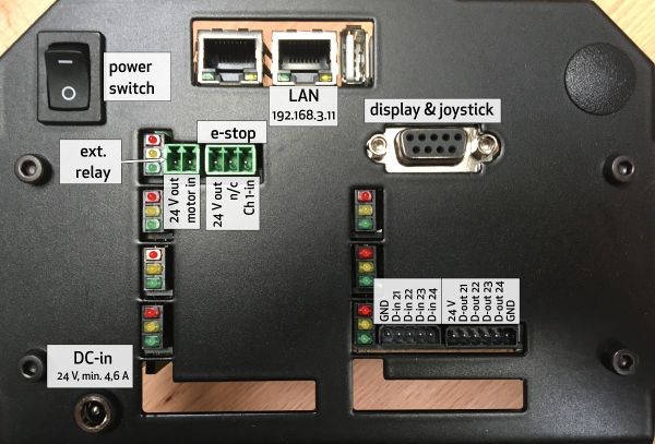
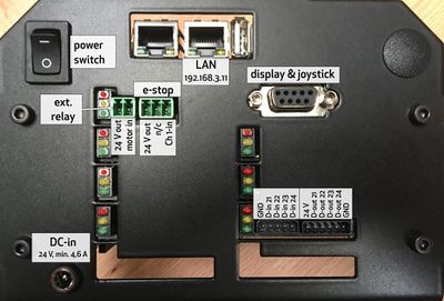
For robolink DCi sold since 2019:
3 additional inputs and outputs are accessible from inside the robot base (DIn25-27 and DOut25-27).
Switch on and move
- Once you have unpacked your DCi Robot, place it on a level surface, remove all zip-ties that hold the robot in the shipping position and all packaging material from the robot arm. Make sure that there is sufficient free space around the robot to operate the arm.
- Connect the Teach Pendant (that is what we call the remote control with the display) to the rear of the robot and tighten the fixing screws of the connector.
- The robot requires a power supply rated for 24V and minimum 4A. A power supply is usually shipped with the DCi robot. Connect it to the back of the robot.
- Connect the power supply to the mains and switch on the robot at the rear.
- The LEDs at the back of the robot will light up and the Teach Pendant will initialize.
- After 20s most of the green LEDs at the back of the robot should be blinking. This indicates that communication has been established to the stepper motor modules and the digital input/output module(s).
- If the red emergency stop button is depressed, disengage it by rotating and pulling upwards at the button.
- Next to a status message, you should see two soft-buttons in the touch display: Reset and Enable. Click Reset, followed by Enable to reset the robot and enable the motors.
- Now there should be a red message in the display saying that the robot is not referenced yet. We will ignore that for now and do the referencing later.
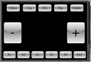
- Push the "Jog" Menu button at the top of the touch display.
- Using the joystick, you should now be able to jog the first, second and third axis to verify their function (slowly rotate the joystick left and right, up-down, left-right).
- Push A5 at the bottom of the screen to gain control of joint 4 and 5. Move it by rotating the joystick left and right, up-down.
Reference
The software that is running on the embedded robot control needs to know what position the robot is in. At the moment it does not. Therefore we need to reference the robot. There is a whole article on referencing the robolink robots in this wiki. In short:
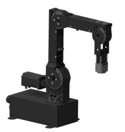
- Move the robot close to its reference switch position: each axis has a metal pin in the joint that is used to sense the reference position. Since you are doing this step for the first time and the robot might still be "folded up" for shipping, jog the joints until the robot is in this position (see image on the right).
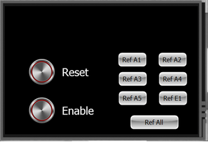
- On the display, select the "Enable" button at the top to open the referencing dialog.
- Start by pushing "Ref A1". Once the joint has stopped moving, continue with joint A2, A3 and so forth.
- After, once the robot has stopped moving, i.e. the referencing has finished, push Reset and Enable the robot again to apply the reference values that have been found during the referencing operation.
Run a program
The DCi robots come with a test program. Once the robot is referenced,
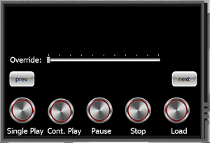
- push the "Play" button at the top of the display to get to the program dialog.
- To run the program press "Single Play". - Ensure that there is sufficient free space around the robot to avoid collisions.
- The robot should play the pre-recorded program.
- In order to run a program continuously, you can push the "Cont. Play" button instead.
- The Override slider sets the speed as a percentage of the maximum speed configured in the firmware.
DIO Module PinOut
Before 2019
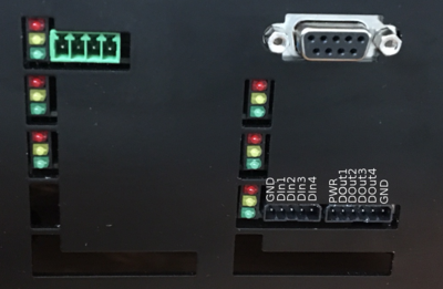
The digital I/O module can be used to operate, e.g. a gripper attached to the robot or to communicate with the external world.
- PWR: linked though to internal 24V supply voltage.
- GND: linked through to internal ground.
- DIn1-4: digital inputs 1-4. Going via 12k into opto-coupler: https://www.vishay.com/docs/84181/tcmt4100.pdf
- DOut1-4: digital outputs 1-4. Going directly into relay: http://omronfs.omron.com/en_US/ecb/products/pdf/en-g3vm_62c1_f1.pdf, which switches internal 24V Supply Voltage through to Dout1-4.
In the CPRog Software, the pins labelled
- DOut 1-4 are addressed with DOut21 - DOut24.
- DIn 1-4 are addressed with DIn21 - DIn24
Once you write a program (see section below), you can address the inputs and outpouts as described here
Since 2019
The digital I/O module can be used to operate, e.g. a gripper attached to the robot or to communicate with the external world.
- PWR: linked though to internal 24V supply voltage.
- GND: linked through to internal ground.
- DIn21-24: digital inputs to read high/low signals from external/additional devices. Going via 12k into opto-coupler: https://www.vishay.com/docs/84181/tcmt4100.pdf
- DOut21-24: digital outputs to switch external/additional devices. Going directly into relay: http://omronfs.omron.com/en_US/ecb/products/pdf/en-g3vm_62c1_f1.pdf, which switches internal 24V Supply Voltage through to Dout1-4.
Once you write a program (see section below), you can address the inputs and outpouts as described here
Connect the robot to a Windows PC to start recording/writing your own programs
In order to generate your own programs, it is best to connect it to a Laptop or PC running Windows. This will allow you to record/generate a program or path that can later be uploaded to the embedded robot control, so that the laptop is no longer required for operation.
Initially, please install iRC on your Windows PC
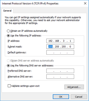
To establish a connection between Linux embedded control and PC, the Network adapter of the PC has to be configured for an IP in the address range 192.168.3.0/24. I usually chose IP address 192.168.3.1 as shown below.
- Power off the robot. Disconnect the power supply from mains power.
- Plug the LAN cable into the right LAN socket at the DCi robot and into your Windows computer on the other end.
- Power on the Robot, disengage emergency stop.
- Wait until the Green LEDs of the stepper motor boards at the back of the robot start blinking.
- Start CPRog and open the correct project file for your robot.
- Connect DCi Robot/TinyCtrl to a Laptop via LAN.
- click Connect, reset, enable. The robot should now be ready for referencing, which can be done via the Teach Pendant. However, since CProg is already running, I would now reference the Robot in CPRog (but that's just personal preference).
Once referenced, you can start recording a program as shown in the video below and this article: CPRog Examples.
For details on the available commands, have a look at
- Command Reference EN: CPRog Command Reference
More details regarding general operation can be found here:
- Documentation / Manual EN: robolink User Guide
- Documentation / Manual DE: robolink Bedienungsanleitung
