Difference between revisions of "Modbus Server"
m (Added S7 usage example) |
|||
| (5 intermediate revisions by the same user not shown) | |||
| Line 15: | Line 15: | ||
The Modbus server is implemented in TinyCtrl version V980-12-018 and newer. Please upgrade your integrated robot control to the current version. | The Modbus server is implemented in TinyCtrl version V980-12-018 and newer. Please upgrade your integrated robot control to the current version. | ||
| − | + | In versions 12 and 13 using the Modbus server requires a license for each robot control. More information can be found [https://rbtx.com/de/components/software/modbus-tcpip on RBTX]. Since version 14 it can be used without a license. | |
Without a license the Modbus features can be tested for 30 minutes. Another test duration can be started by restarting the robot. | Without a license the Modbus features can be tested for 30 minutes. Another test duration can be started by restarting the robot. | ||
| Line 40: | Line 40: | ||
As demonstration and example for operation with Siemens S7 1200/1500 a program block can be downloaded. The library contains a function block that covers the communication with the robot control. It is available here: | As demonstration and example for operation with Siemens S7 1200/1500 a program block can be downloaded. The library contains a function block that covers the communication with the robot control. It is available here: | ||
[https://www.cpr-robots.com/download/CPRog/CPR_ROBOTS_TiA_Lib_V01-06.zal16 CPR_ROBOTS_TiA_Lib_V01-06.zal16] | [https://www.cpr-robots.com/download/CPRog/CPR_ROBOTS_TiA_Lib_V01-06.zal16 CPR_ROBOTS_TiA_Lib_V01-06.zal16] | ||
| + | You will need TiA version 16 or newer. [https://www.cpr-robots.com/download/CPRog/ModbusTest.zap16 ModbusTest.zap16] contains usage examples. | ||
If you are updating the block please also update the DataTypes in the block. | If you are updating the block please also update the DataTypes in the block. | ||
| Line 61: | Line 62: | ||
= Digital inputs and outputs = | = Digital inputs and outputs = | ||
| − | * Digital inputs can be read on discrete inputs | + | * Digital inputs can be read on discrete inputs 364-427 and as bitsets on input registers 207-210. |
| − | * Digital outputs can be read | + | * Digital outputs can be read and changed on coils 300-363 and as bitsets on holding registers 207-210. |
| + | * Global signals can be read and changed on coils 200-299 and as bitsets on input registers 200-206. | ||
| − | = | + | = Communicating with Robot Programs = |
| − | + | ||
| − | * Global signals | + | To communicate with the robot program a PLC can use the following mechanisms: |
| − | + | * Global signals - boolean values similar to digital inputs / outputs | |
| − | + | * Number variables - 16 bit integer values | |
| + | * Position variables - a set of joint angles and cartesian position | ||
| + | |||
| + | == Global Signals == | ||
| + | Global signals can be read or changed via coils 200 (GSig1) - 299 (GSig100). You can also access global signals as 16 bit fields via holding registers 200 - 206. | ||
| + | |||
| + | == Number Variables == | ||
| + | Number variables exchange 16 bit integer values. Read and write directions are split: there are 16 variables that can be read by the PLC (mb_num_r1 - mb_num_r16 in input registers 440 - 455) and 16 that can be written (mb_num_w1 - mb_num_w16 in holding registers 440 - 455). | ||
| + | |||
| + | == Position Variables == | ||
| + | Position variables consist 16 succeeding register containing 6 robot axis values, 3 external axis values, cartesian XYZ coordinate and ABC orientation. Like the number variables there are 16 for reading (mb_pos_r1 - mb_pos_r16 in input registers 456 - 711) and 16 for writing (mb_pos_w1 - mb_pos_w16 in holding registers 456 - 711). | ||
| + | |||
| + | The register order for each position variable is the following (example register numbers for position variable 1, the next variable follows directly after): | ||
| + | * robot axes 1 - 6 (456 - 461) | ||
| + | * external axes 1 - 3 (462 - 464) | ||
| + | * X, Y, Z (465 - 467) | ||
| + | * A, B, C (468 - 470) | ||
| + | |||
| + | Each register value has precision 0.1, e.g. a register value of 1234 means value 123.4 degrees or mm. | ||
= Moving Robots via Modbus = | = Moving Robots via Modbus = | ||
| Line 77: | Line 97: | ||
The article [[Moving Robots via Modbus]] gives a more in-depth explanation on how to move a robot. | The article [[Moving Robots via Modbus]] gives a more in-depth explanation on how to move a robot. | ||
| − | [[Category:TinyCtrl]][[Category:Modbus]] | + | [[Category:Configuration]][[Category:TinyCtrl]][[Category:Modbus]] |
Latest revision as of 10:28, 17 May 2024
The Modbus protocol can be used for controlling robots among other devices from a central PLC to achieve a combined workflow. A register mapping defines sets of 1-bit and 16-bit registers that can be read for information or written to send parameters, change states or start actions.
The embedded robot control TinyCtrl supports Modbus TCP. This article gives a short overview of the features, a more in-depth explanation can be found in the user manual.
Programming blocks for Siemens S7-1200 and S7-1500 will be provided for easy integration of basic features.
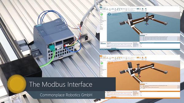
Introduction Video
Video Link: Modbus Interface Video on YouTube
Availability
The Modbus server is implemented in TinyCtrl version V980-12-018 and newer. Please upgrade your integrated robot control to the current version.
In versions 12 and 13 using the Modbus server requires a license for each robot control. More information can be found on RBTX. Since version 14 it can be used without a license.
Without a license the Modbus features can be tested for 30 minutes. Another test duration can be started by restarting the robot.
Documentation
The robot control user guide covers the Modbus Interface in a seperate chapter of 10 pages with alle necassary information. The latest version can be downloaded here: DocumentationEN
Here you can find the Modbus mapping as a spread sheet. Details on the data format is explained in the user guide.
This Wiki page contains the starting points and downloadable material, but for the complete depth of details please refer to the user guide.
Setting up the Modbus server
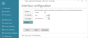
By default the Modbus server is disabled. It can be enabled using CPRog/iRC.
- Connect CPRog/iRC to the robot by clicking "Connect"
- Click File -> Configure Interfaces -> Modbus.
- Check the box "Enabled" to enable the server.
- Change the port and maximum number of connections if necessary.
- Click "Apply" or "Save Project" below the configuration to apply the changes. The Modbus server will start immediately.
PLC integration
As demonstration and example for operation with Siemens S7 1200/1500 a program block can be downloaded. The library contains a function block that covers the communication with the robot control. It is available here: CPR_ROBOTS_TiA_Lib_V01-06.zal16 You will need TiA version 16 or newer. ModbusTest.zap16 contains usage examples. If you are updating the block please also update the DataTypes in the block.
This block is generic and will not fit to every application. Therefore it provided with access to the code so that it can be adapted to the use case. The block covers most of the available data, this leads to longer communication times. If your application requires only few variables in low cycle times we recommend to adapt the function block to your needs, especially reduce the number of transferred variables.
The Modbus interface can also be used with different PLC types, the necessary information are found below and in the documentation.
Modbus mapping
The Modbus protocol defines 4 access types that generally refer to distinct sets of parameters:
- Discrete inputs (1 bit, read only)
- Coils (1 bit, read/write)
- Input registers (16 bit, read only)
- Holding registers (16 bit, read/write)
Our mapping uses these depending on what access type is appropriate for what information. Status information can be read from discrete inputs and input registers, states can be changed by writing to coils and holding registers, actions can be startet by writing to coils.
A complete mapping table can be found in the user manual.
To test whether the Modbus connection is successful the input registers on addresses 0-3 can be read: These contain the TinyCtrl version and mapping version, e.g. 980, 12, 20, 1.
Digital inputs and outputs
- Digital inputs can be read on discrete inputs 364-427 and as bitsets on input registers 207-210.
- Digital outputs can be read and changed on coils 300-363 and as bitsets on holding registers 207-210.
- Global signals can be read and changed on coils 200-299 and as bitsets on input registers 200-206.
Communicating with Robot Programs
To communicate with the robot program a PLC can use the following mechanisms:
- Global signals - boolean values similar to digital inputs / outputs
- Number variables - 16 bit integer values
- Position variables - a set of joint angles and cartesian position
Global Signals
Global signals can be read or changed via coils 200 (GSig1) - 299 (GSig100). You can also access global signals as 16 bit fields via holding registers 200 - 206.
Number Variables
Number variables exchange 16 bit integer values. Read and write directions are split: there are 16 variables that can be read by the PLC (mb_num_r1 - mb_num_r16 in input registers 440 - 455) and 16 that can be written (mb_num_w1 - mb_num_w16 in holding registers 440 - 455).
Position Variables
Position variables consist 16 succeeding register containing 6 robot axis values, 3 external axis values, cartesian XYZ coordinate and ABC orientation. Like the number variables there are 16 for reading (mb_pos_r1 - mb_pos_r16 in input registers 456 - 711) and 16 for writing (mb_pos_w1 - mb_pos_w16 in holding registers 456 - 711).
The register order for each position variable is the following (example register numbers for position variable 1, the next variable follows directly after):
- robot axes 1 - 6 (456 - 461)
- external axes 1 - 3 (462 - 464)
- X, Y, Z (465 - 467)
- A, B, C (468 - 470)
Each register value has precision 0.1, e.g. a register value of 1234 means value 123.4 degrees or mm.
Moving Robots via Modbus
The Modbus server offers two approaches for moving the robot:
- Position variables: Write your position as joint angles or cartesian position to a position variable, then use a robot program with a Join-by-Variable or Linear-by-Variable command to move to the position.
- The mapping provides registers for motion target positions (joint angles or cartesian positions). By writing 1 to a specific coil address a cartesian, joint or relative motion can be started. Please refer to the mapping table in the user manual.
The article Moving Robots via Modbus gives a more in-depth explanation on how to move a robot.

