Difference between revisions of "Define the zero position offsets"
m (changed link) |
|||
| (65 intermediate revisions by 3 users not shown) | |||
| Line 1: | Line 1: | ||
| − | The robolink arms provide reference switches which allow a precise and reproducible referencing. The reference switches are inductive switches | + | Requirements: CPRog V902-10-032 or higher. See [[Software Updates]]. TinyCtrl V980-04-039. See [[TinyCtrl Downloads]]. |
| − | The | + | |
| + | |||
| + | The robolink arms provide reference switches which allow a precise and reproducible referencing. The reference switches are inductive switches reacting to metal pins as set points (motor encoder version) or hall-effect sensors reacting to magnets as set points (AE version). | ||
| + | |||
| + | The positions of the sensors at the joints of the robot are not the [[#Move the robot into zero position|zero positions of the joints]]. Each joint module stores an offset value that defines the difference between the reference position and the zero position. The offset values are the number of encoder pulses between these two positions. | ||
| + | |||
| + | <span style="color:#008000"> When the combination of robot and control electronics have been provided by CPR, then these offsets are already defined in the modules. They are also written down on the quality assurance sheet. </span> | ||
| + | |||
| + | <span style="color:#800000"> If robot and control have been supplied separately, we wouldn't have been able to do this calibration for you. Therefore the following steps should be performed.</span> | ||
| + | |||
| − | |||
This page shows how to find the offsets for your robot and how to set the into the joints modules. | This page shows how to find the offsets for your robot and how to set the into the joints modules. | ||
| + | =Backup the Current Firmware Parameter= | ||
| + | [[File:CPRogAmpConfig.JPG|400px|thumb|Backup Amp Configuration menu entry in CPRog]] | ||
| + | To find the correct offsets, we need to know the current values: | ||
| + | * Download your current firmware parameter from the electronic modules: | ||
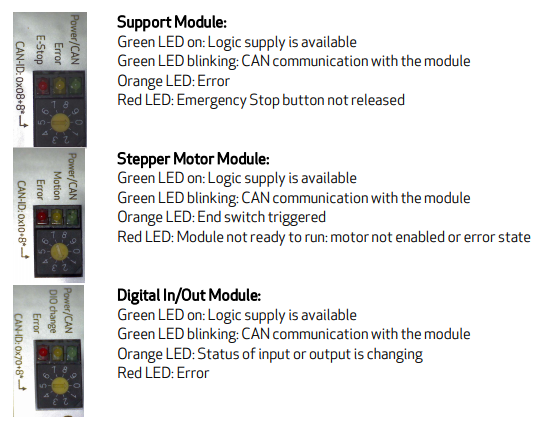
| + | # Start CPRog and "Connect" with the robot control electronics. Most of the [[media:DIN-Rail-Module-LEDs.png|green LEDs]] of the robot control electronics should be blinking now. | ||
| + | # Open the CPRog menu on the circle in the upper left corner and press the menu item "Configuration --> Amp Config --> Backup current Config" | ||
| + | # Now CPRog loads the current parameter set from the modules and stores them in <code>c:\CPRog\Data\Backup\AmpParamBackup_yourdateandtime.dat</code> | ||
| + | # Make a copy of this file so that you are able to restore the old data | ||
| − | + | <br clear=all> | |
| − | + | =Reference the robot= | |
| − | |||
| − | |||
| − | |||
| − | |||
| − | |||
| − | |||
| + | Perform a referencing of the robot arm. Follow the instructions on page [[Referencing robolink]]. | ||
| − | + | =Move the robot into zero position= | |
| − | + | [[File:Robolink_5SV_ZeroPosition.PNG|400px|thumb|Zero position of the robolink 5DOF SV robot]] | |
| − | |||
| − | + | Now we jog the robot arm into the zero position to find the offsets between reference position and zero position. | |
| − | + | * Start CPRog and connect / reset / enable the robot arm | |
| − | * | + | * Jog the robot into the zero position as shown in the picture on the right. Joint 1 points into +X direction, joint 2 points upwards, joints 3 and 4 point forward into +X direction. |
| + | * At first move with e.g. 30% [[override]]. Then do the fine tuning with e.g. 5% [[override]]. Use a spirit level or a laser tool to make sure you are in the zero position. | ||
| + | ** Note: the joint '''holes''' define the zero position, not the sheet metal surfaces! | ||
| + | * The fifth axis should be set according to the connected gripper. If no gripper is connected, mark the zero position and set to this. | ||
| + | * Press the "Reset" button in CPRog to load the current hardware position. | ||
| + | <br clear=all> | ||
| − | + | =Calculate the offsets= | |
| − | + | Now we can see the offset in degree in the CPRog user interface. But we need to calculate the offset in encoder tics. | |
| − | |||
| + | * Open the Microsoft Excel file [https://www.cpr-robots.com/download/CPRog/FindingTheOffset_robolink.xlsx FindingTheOffset_robolink.xlsx] | ||
| + | ** also found in c:\CPRog\Data\Robots\FindingTheOffset.xlsx | ||
| + | ** Last file version: Dec. 06th, 2019 | ||
| + | * In the file choose the right [[Configuration_Files_Overview#Which_files_do_I_need_for_my_robot_.28example.29.3F|robot type]] | ||
| + | * Follow the instructions in the sheet | ||
| + | * Attention: The offset values written in the AmpParameter file are numbers (no decimal . or ,) | ||
| − | + | =Uploading the offsets to the modules= | |
| − | + | Now we set the new offsets in the .dat file that we backuped before and upload them to the modules. | |
| − | |||
| + | * Open the .dat file from above and set the "Offset" values as calculated in the table. Use only numbers! (no decimal values, no "," or ".") | ||
| + | * Save the .dat file and upload the parameter: | ||
| + | # Open the CPRog menu on the circle in the upper left corner and press the menu item "Configuration --> Amp Config --> Set new Configuration" | ||
| + | # Confirm the upcoming warning, choose the updated .dat file you just changed and press "OK" | ||
| + | # Now the parameter with the new offsets are uploaded to the modules. You can see the green LED of each module blinking for a second, then the next. | ||
| + | =Final Test= | ||
| − | + | The new offsets should be verified: | |
| − | + | * Switch off the robot control electronics and CPRog | |
| − | * Switch off the robot control | + | * Wait at least 5 seconds to start the control electronics and CPRog again |
| + | * Connect / Reset / Enable the robot | ||
| + | * Reference the robot | ||
| + | * Jog the robot so that all joint values are zero. The real robot should be in the zero position now. | ||
| + | =Documentation= | ||
| + | * Please write down the offsets or store the .dat file in a folder different then the CPRog program directory. When you update CPRog you custom .dat file might be overwritten. So it is necessary to store your custom file in a different location. | ||
| − | |||
| − | + | For questions or comments please get [[Support Routes|into contact with us]] | |
| − | + | [[Category:CPRog]] | |
| − | + | [[Category:CPRog v980-10-XXX]] | |
Latest revision as of 11:03, 16 August 2023
Requirements: CPRog V902-10-032 or higher. See Software Updates. TinyCtrl V980-04-039. See TinyCtrl Downloads.
The robolink arms provide reference switches which allow a precise and reproducible referencing. The reference switches are inductive switches reacting to metal pins as set points (motor encoder version) or hall-effect sensors reacting to magnets as set points (AE version).
The positions of the sensors at the joints of the robot are not the zero positions of the joints. Each joint module stores an offset value that defines the difference between the reference position and the zero position. The offset values are the number of encoder pulses between these two positions.
When the combination of robot and control electronics have been provided by CPR, then these offsets are already defined in the modules. They are also written down on the quality assurance sheet.
If robot and control have been supplied separately, we wouldn't have been able to do this calibration for you. Therefore the following steps should be performed.
This page shows how to find the offsets for your robot and how to set the into the joints modules.
Backup the Current Firmware Parameter

To find the correct offsets, we need to know the current values:
- Download your current firmware parameter from the electronic modules:
- Start CPRog and "Connect" with the robot control electronics. Most of the green LEDs of the robot control electronics should be blinking now.
- Open the CPRog menu on the circle in the upper left corner and press the menu item "Configuration --> Amp Config --> Backup current Config"
- Now CPRog loads the current parameter set from the modules and stores them in
c:\CPRog\Data\Backup\AmpParamBackup_yourdateandtime.dat - Make a copy of this file so that you are able to restore the old data
Reference the robot
Perform a referencing of the robot arm. Follow the instructions on page Referencing robolink.
Move the robot into zero position

Now we jog the robot arm into the zero position to find the offsets between reference position and zero position.
- Start CPRog and connect / reset / enable the robot arm
- Jog the robot into the zero position as shown in the picture on the right. Joint 1 points into +X direction, joint 2 points upwards, joints 3 and 4 point forward into +X direction.
- At first move with e.g. 30% override. Then do the fine tuning with e.g. 5% override. Use a spirit level or a laser tool to make sure you are in the zero position.
- Note: the joint holes define the zero position, not the sheet metal surfaces!
- The fifth axis should be set according to the connected gripper. If no gripper is connected, mark the zero position and set to this.
- Press the "Reset" button in CPRog to load the current hardware position.
Calculate the offsets
Now we can see the offset in degree in the CPRog user interface. But we need to calculate the offset in encoder tics.
- Open the Microsoft Excel file FindingTheOffset_robolink.xlsx
- also found in c:\CPRog\Data\Robots\FindingTheOffset.xlsx
- Last file version: Dec. 06th, 2019
- In the file choose the right robot type
- Follow the instructions in the sheet
- Attention: The offset values written in the AmpParameter file are numbers (no decimal . or ,)
Uploading the offsets to the modules
Now we set the new offsets in the .dat file that we backuped before and upload them to the modules.
- Open the .dat file from above and set the "Offset" values as calculated in the table. Use only numbers! (no decimal values, no "," or ".")
- Save the .dat file and upload the parameter:
- Open the CPRog menu on the circle in the upper left corner and press the menu item "Configuration --> Amp Config --> Set new Configuration"
- Confirm the upcoming warning, choose the updated .dat file you just changed and press "OK"
- Now the parameter with the new offsets are uploaded to the modules. You can see the green LED of each module blinking for a second, then the next.
Final Test
The new offsets should be verified:
- Switch off the robot control electronics and CPRog
- Wait at least 5 seconds to start the control electronics and CPRog again
- Connect / Reset / Enable the robot
- Reference the robot
- Jog the robot so that all joint values are zero. The real robot should be in the zero position now.
Documentation
- Please write down the offsets or store the .dat file in a folder different then the CPRog program directory. When you update CPRog you custom .dat file might be overwritten. So it is necessary to store your custom file in a different location.
For questions or comments please get into contact with us